
- Home
- About
- Products
Motion controller
CM600 RTCP 6-Axis Motion controll
CM300 R 3-Axis Motion controller
CM300 3-Axis Motion controller
- Download
- Support
- Applications
Secondary Development
The DXF page: enable the feature and import a drawing
Download the bilingual offline manual (ZIP, 16.7 MiB, original images and example attachments)
DXF topic: DXF page and import → Hole table and settings → DXF postprocessing → G196 bore-milling example
Machining Wizard calculates a path from entered dimensions; DXF takes positions from a drawing and adds machining settings. Both eventually return a program to the standard program page.
This chapter explains how the existing DXF entry, page and import script work together. Use the same four-hole drawing throughout this four-chapter topic. Continue with the hole table, postprocessing, then the G196 extension.
1. Enable DXF in the macro parameter window
The DXF switch is
#929.item[12]. It is currently absent from the configuration menu: edit it yourself in the macro parameter window.- Sign in with developer permissions and open Parameter on the main screen.
- Open Macro Param. in the function-key area. Positions are configurable, so find the function by name rather than assuming a fixed F-key. If it is not assigned to the panel, use the method in Function-key configuration to select it.
- Find 929 in the parameter list and click its row. The upper table shows the parameter's main fields; the lower table shows its items.
- Find
#929.item12in the item table. This spelling omits the brackets; it identifies the same item as#929.item[12]in a script. - Change that row's item value to the enabled choice, numeric value 1. Do not change parameter 929's main value, title, type or version.
- Close the window. DXF appears on the main navigation bar. Exit the application normally when configuration is complete so the settings follow its normal save process.
The current English language pack retains Chinese text for some fields, including this item: DXF导图 is the DXF feature, 否 means No (0), and 是 means Yes (1). The screenshots preserve those actual labels.
#929.item[12]Main-screen result 0 / No ( 否)Hide the DXF entry 1 / Yes ( 是)Show the entry and allow the DXF page to be opened 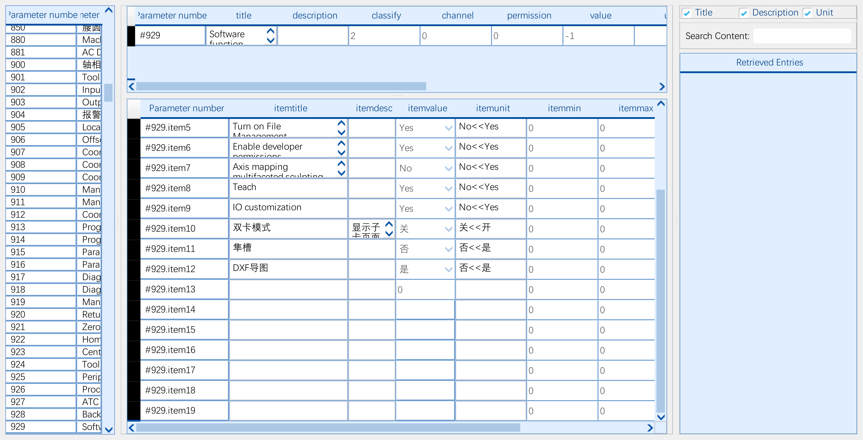
Click the screenshot to view the original image.

Click the screenshot to view the original image.
The switch controls entry and page visibility. It does not choose a hole depth, tool number or coordinate system, or turn the drilling page into a contour-machining page.
2. Use four circles to understand the page
Download the four-hole DXF. It contains four independent circles, all on Z=0, without additional contours.
Initial number Center X Center Y DXF radius Actual diameter NO.1 10 10 2 4 NO.2 40 10 2 4 NO.3 10 35 2 4 NO.4 40 35 3 6 Click DXF on the main navigation bar, then Import DXF, and choose this file. DXF is a main entry alongside Program, not a fourth child page after Toolpath Preview, File Management and Machining Wizard.
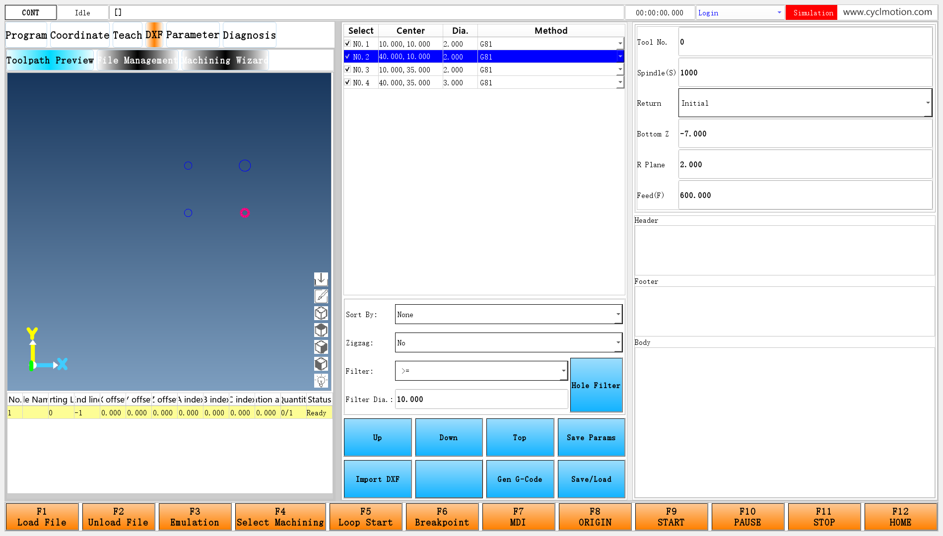
Click the screenshot to view the original image.
Figure 3: NO.2 is selected and its Bottom Z has been changed to −7. The other holes use −5. Drag the page dividers to give the table and input area enough space.
Area What it contains Drawing area Imported circles and the connections drawn between holes during generation Hole table Selection, center, geometric size and G81/G82/G83 method Upper-right settings Tool, spindle speed, bottom Z, R plane, feed and other values for the selected hole Sorting and filtering Which holes participate and how their positions are ordered Header and Footer Fixed text before and after the generated section Body The complete editable text produced by Gen G-Code, including header and footer In this version, the column labelled “Dia.” actually displays the DXF circle radius. The first three circles therefore show 2 and the fourth shows 3. Filter Dia. uses that same radius value. This chapter keeps the actual interface wording and explains the numbers the implementation reads.
3. How the entry becomes visible and the page loads
In
env/maininterface/maininterface.ui, the DXF label is namedlabel_49. Its relevant attributes are:-A: (clickedEvent:/env/dxfpage[0](#810permission=7)) -C(#929item12==1) -V0Read them in this order:
#929item12==1tests whether the DXF switch is on.-V0uses condition 0 to control visibility; the entry is visible when it is true.- A click sets
#810.permission=7to select DXF, then runs/env/dxfpage. [0]selects the main Qt script channel, as in the earlier main-page examples.
Here is the complete
env/dxfpagescript:IF#899.version==1GOTO1 #899.version=1 #899.itemdesc[0]="/env/dxf/dxf.ui" widgetFunc["QFrame","dxfframe","refresh",""] N1#899.itemdesc[0]supplies the UI path. The main window'sdxfframeloads that page. Here,#899.versionmeans “already loaded,” avoiding reconstruction on every click. The main frame also checks#810.permission==7and the DXF switch when deciding whether to display the area.This repeats the multipage method: the entry changes a page-selection parameter, the frame controls visibility, and a script loads the UI on first use.
4. Match the buttons to their scripts
The page file is
env/dxf/dxf.ui. Use this table to find the starting point for each operation.Native control Object name Script Main result Import DXF pushButton_43dxfloaderRead geometry, build the hole list and copy defaults to every hole Up / Down / Top pushButton_5/pushButton_34/pushButton_3uppath/downpath/headpathChange which hole number each displayed row refers to Save Params pushButton_35saveDrillParamMake the current hole's settings the defaults for later imports Hole Filter pushButton_37holeselectReset hole checkmarks according to a size comparison Gen G-Code pushButton_44generatecodeCollect per-hole settings, generate text and refill Body Save/Load pushButton_42loadgcodeSave Body to an NC file and hand it to the existing program page All scripts in this table are under
env/dxf/. Import DXF and Save/Load use mouse-release events; the other listed buttons use click events. When tracing a button, inspect its event attribute rather than guessing a filename from its caption.This topic also includes the complete import script, generation script and save/load script, for reading alongside this chapter and the following chapters.
5. What importing a drawing actually creates
dxfloaderopens a file picker, then uses two built-in operations. Its opening section is:#100="" widgetFunc["openFileName","*.dxf","",100] IF#100==""GOTO2 widgetFunc["readDxf",#100,"",0]#100receives the selected path. The script then joins#6002.item[0]through#6002.item[9]into a colon-separated string of default settings and calls:widgetFunc["dxfDrillInit","","",#6001.description]The responsibilities are distinct:
readDxfreads geometry. File entities enter the software's internal drawing data.dxfDrillInitcreates the drilling list. It extracts centers and radii from circle entities across the drawing's layers, creates#6001records and draws the circles.dxfloaderprepares per-hole settings. It allocates one item per hole in#6003through#6012, then copies defaults, input types and option text from#6002.
Reading an entity does not automatically make it a drilling hole. This page selects circle entities. A closed polyline or several arcs that look like a circle do not automatically enter this hole list. The page also has no input for choosing holes by layer name.
Reimporting rebuilds the list and per-hole settings and clears the old Body text. Save an NC result before reimporting if you want to keep it. To keep a set of defaults, select the appropriate hole and click Save Params first.
Read the import script's two loops
The configuration does not allocate ten consecutive parameter numbers for each hole. Each setting has one parameter number; different holes occupy its different items. All bottom-Z values are in
#6007, for example, and all feeds are in#6012.The import script first clears the item counts of
#6003through#6012, then sets each count to the number of holes. Its outer loop visits holes; its inner loop copies the settings:#[6003+#6002.channel].itemunit[#6002]=#6002.itemunit[#6002.channel] #[6003+#6002.channel].itemtype[#6002]=#6002.itemtype[#6002.channel] #[6003+#6002.channel].item[#6002]=#6002.item[#6002.channel]Here the main value of
#6002temporarily holds the hole index, and#6002.channelholds the setting index. The defaults themselves remain in#6002.item[...]. For the original NO.2's feed, the hole index is 1 and the setting index is 9, so the third line means:#6012.item[1]=#6002.item[9]The first two lines also copy the input type and option labels. Copying defaults therefore involves more than values: to create a combo box, the table needs an option-type definition and its choice names. After import, every hole has its own values; editing NO.2 changes neither the defaults nor NO.1.
6. Troubleshooting
Symptom First check No DXF entry Inspect #929.item[12]in the macro parameter window, not just the configuration menuA circle-shaped object is absent from the table Confirm that its entity is a circle; polylines are not automatically treated as holes Imported holes now have indices and their own default settings. The next chapter uses those values to explain table selection, drawing highlights and the right-hand inputs.
Previous lesson: Machining Wizard · Reading guide · Next lesson: Hole table and settings
Online - Download
