
- 首页
- About
- Products
- Download
- Support
- Applications
Secondary Development
The hole table: connect the list, drawing and machining settings
Download the bilingual offline manual (ZIP, 16.7 MiB, original images and example attachments)
DXF topic: DXF page and import → Hole table and settings → DXF postprocessing → G196 bore-milling example
After enabling DXF and importing the four circles, the standard page has a drawing, a hole table and settings for the selected hole. This chapter explains how those three areas use the same hole index.
Start with the original four-hole drawing. Follow NO.2 at center 40,10: change its depth independently, pick holes in the drawing, then reorder and filter the list. The later code-generation example uses G81, Bottom Z −7 for this hole and −5 for the others.
1. How a table row finds its own settings
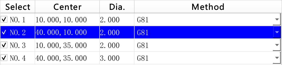
Click the screenshot to view the original image.
A useful table technique is used here: the displayed row and the original hole number are stored separately. Moving rows therefore leaves machining settings attached to the correct hole.
Let
rmean the displayed row andpmean the original hole index:p = #6001.itemversion[r]This is an explanatory relationship, not a script line to paste with literal variables named
randp.Location Meaning on this page #6001.itemnumNumber of imported holes #6001.itemversion[r]Original hole represented by displayed row r #6001.itemmin[p]Hole selection: 1 included, 0 excluded #6001.itemtitle[p]Center and radius text for hole p #6001.itemdesc[p]Hole p's settings joined into text before generation #9048.versionCurrently selected original hole index #6001.channelDisplay row recorded by a table click or move script; picking in the view does not automatically update it Here,
itemversionstores ordering anditemminstores a checkmark. Their names do not mean “software version” or “minimum hole size” in this design. The consuming scripts and controls determine the purpose of these fields.The Center column uses this click attribute:
-事件: (clickedEvent:/env/dxf/selectDrillItem[1](#9048version=#6001itemversion%%<<#6001channel=%%))%%is the row. A click writes the original hole index and displayed row before callingselectDrillItem. That script file is currently empty, yet selection works because the essential assignments are inside the event attribute.The Bottom Z input then uses:
-T(#6007item[#9048version])
-D
Selecting the original NO.2 gives
#9048.version=1, so the input reads and writes#6007.item[1]. Changing it to −7 leaves other holes at −5. Reordering the table still addresses the same original hole.2. How the table creates controls for each hole
entityTableis a nativeQTableWidget. Its attributes define the headers and the rules for creating each row, rather than four permanently placed rows. These row settings:-rows:#6001itemnum -serial:0make the row count follow the number of holes, with
%%starting at 0. The four columns obtain their contents as follows:Column Key expression in the original attributes Purpose Select -T11(#6001itemmin[#6001itemversion%%]<<"NO."<<%%+1)Explicitly creates a checkbox; stores its value by original hole index, but numbers NO. by displayed row Center -参数(#6001itemtitle[#6001itemversion%%]*")"/"(")Extracts the center text between parentheses in the title Dia. -参数(#6001itemtitle[#6001itemversion%%]/","/":")Extracts the size from the same title; the current value is a radius Method -参数(#6003item[#6001itemversion%%])Creates an editor from the item's input type; the existing definition produces the G81/G82/G83 combo box For example, the title
center(40.000,10.000),arc radius:2.000gives Center 40.000,10.000 and Dia. 2.000. This string extraction is a display rule. When generating XY, the built-in operation uses the centers obtained from the drawing, rather than interpreting that title as a geometry file.For the Method column,
itemtypespecifies an option editor,itemunitsupplies its three names, anditemstores 0, 1 or 2. The shared control handler writes a changed selection directly to#6003.item[p]; no separate “save drilling type” script is required. Headers use#1110.itemtitle[11..14], so language packs supply their Chinese and English captions.The row also compares
#9048version==#6001itemversion%%to distinguish the current hole visually. Checking a hole for machining, selecting it for editing, and changing its type are separate actions. If the right-hand inputs still show another hole after you change a row's type, click the target row's Center or Dia. cell to point#9048.versionat it.The same approach works in other pages that select an object in a list and edit its settings beside the list. All columns and side inputs must consistently use the original object index, even after displayed rows move.
3. How the table and drawing select the same hole
Here, the selected hole means the hole you are viewing and preparing to edit. Its original index is stored in
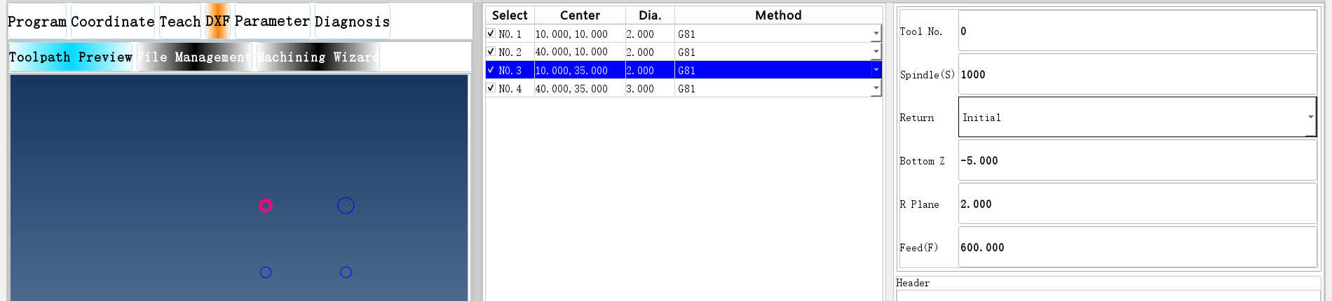
#9048.version. The highlighted table row, highlighted circle and right-hand settings all use that index.In the DXF page overview, Figure 3, clicking the Center cell for 40,10 makes NO.2 blue, highlights its circle in red and magenta, and shows Bottom Z as −7. Now, in the Windows version, move the pointer close to the circumference of the circle centered at 10,35. No mouse button needs to be held down. Selection changes as follows:
Click the screenshot to view the original image.
Figure 2. This continuous crop of the native page shows all three areas. The upper-left circle, the row with center 10,35 and the −5.000 input all refer to original hole 2. The row label is NO.3 because displayed numbering starts at 1. Click the image to enlarge it.
Both routes end at the same parameter:
Click Center or Dia. → itemversion converts row to original hole ─┐
                                                                 ├→ #9048.version
Point at a circle   → built-in picking finds its original index ──┘
                                                                       ↓
                                          Circle highlight, row highlight, settings
From table to drawing. The click attribute already assigns
#9048.version. The built-in drawing area uses that index to highlight the circle. The emptyselectDrillItemtherefore needs no extra script to color the circle. Drawing records retain the original hole index, allowing all the circle's line segments to be identified together.From drawing to table. Mouse tracking is enabled in the Windows drawing area. When the pointer passes over a circle, built-in picking writes its index to
#9048.version. Each table row already contains these attributes:-C1(#9048version==#6001itemversion%%) -C0(1) -DEach row asks whether its original hole index equals the current index. A matching row uses display style 1, which has a blue background in the standard theme; other rows use style 0.
-Dupdates the display as the parameter changes. The Bottom Z input also reads#6007.item[#9048.version], so picking a circle changes its displayed settings too.Built-in picking also records the drawing sequence in
#9047.permission; this page initializes its circles in sequence 0.#9048.versionis a shared drawing-selection field used for the hole index on this DXF drilling page. Do not reuse it as a custom temporary variable. Built-in code handles picking and drawing; configuration attributes handle table colors and input bindings.4. Why selecting a hole still works after reordering
After moving the original NO.2 to the top, the first two rows are:
Display row, zero-based #6001.itemversion[row]Center 0 1 40,10 1 0 10,10 Picking the circle at 10,10 still produces original index 0:
#9048.version=0. The second row highlights because itsitemversionis 0. The input reads#6007.item[0], which remains −5. The picked index does not become “the first displayed row,” and its depth does not move to the hole at 40,10.One detail matters when extending the page: picking in the drawing does not also update
#6001.channelto the corresponding row, and does not callselectDrillItem. Just after moving NO.2 to the top,#6001.channelis 0. Picking the circle at 10,10 can leave it at 0 even though that hole is now in the second row.The existing Up, Down and Top scripts therefore search
itemversionfor the current hole first, record the matching row, and only then move it. The originaluppathsearch uses:IF#6001.itemversion[#6001.permission]==#9048.versionGOTO1On finding a match, it executes
#6001.channel=#6001.permission. See the complete Up script. Custom move, delete or insert actions should also find the row from the current hole index instead of treating an old#6001.channelvalue as the latest graphical selection.Rules to retain when customizing this interaction
- Editing selection and machining inclusion are separate. Circle and row highlights identify the hole being edited.
#6001.itemmin[p]determines machining inclusion. Picking a circle does not check or uncheck it. - Picking follows the circumference. Pointing at the empty center is not the same as picking its circle. Moving to blank space that hits no geometry does not automatically clear the previous selection.
- The blue row comes from attribute conditions. Do not substitute the table's ordinary current row for
#9048.version: that current row can stay unchanged during graphical picking. Highlighting also does not mean automatic scrolling; scroll the list when needed to see the row. - Bind displays that must work from both routes to the same hole index. Additional inputs, names or descriptions should read the hole identified by
#9048.version, with a valid-index condition:0 ≤ index < #6001.itemnum. An update placed only inselectDrillItemcovers the table-click route only.
The table lets users find a hole by its text, while the drawing lets them find it by position. Both routes edit the same per-hole settings.
5. Defaults and per-hole settings
Default Per-hole value; p is the original index Meaning and output #6002.item[0]#6003.item[p]0=G81, 1=G82, 2=G83 #6002.item[1]#6004.item[p]Tool number #6002.item[2]#6005.item[p]Spindle speed, output as S #6002.item[3]#6006.item[p]Initial=0 produces G98; R Plane=1 produces G99 #6002.item[4]#6007.item[p]Bottom Z coordinate #6002.item[5]#6008.item[p]R plane #6002.item[6]#6009.item[p]G82 dwell; the postprocessor multiplies it by 1000 for P #6002.item[7]#6010.item[p]G83 peck depth, output as Q #6002.item[8]#6011.item[p]G83 clearance, output as K #6002.item[9]#6012.item[p]Feed, output as F This example uses G81, Tool No. 0, Spindle(S) 1000, Bottom Z −5, R Plane 2, Feed(F) 600 and Initial under Return, corresponding to value 0. Select a hole and enter these values, click Save Params, then reimport the four-hole drawing. Every hole starts with these defaults. Change only the original NO.2 to Bottom Z −7 afterwards. If Return is blank after the first selection, refresh it as described below before entering the settings.
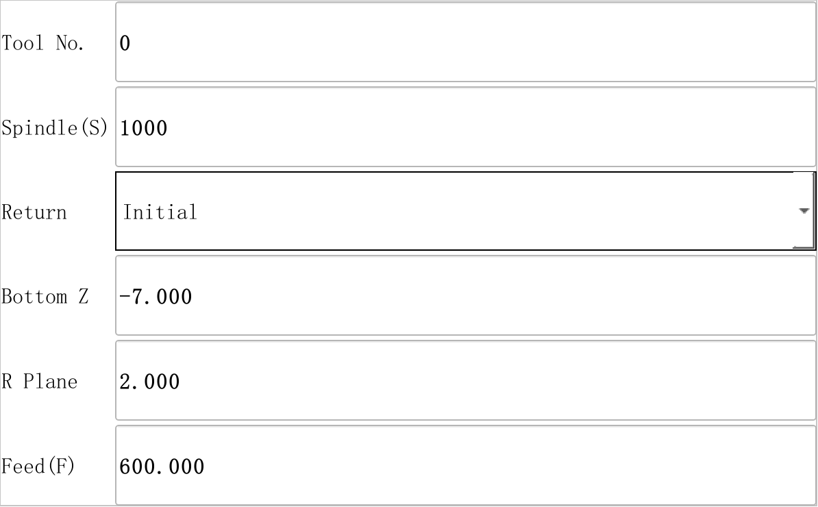
Click the screenshot to view the original image.
Figure 3: Return displays Initial, corresponding to
#6006.item[1]=0for the selected hole and G98 in the generated code. Selecting R Plane writes 1 and produces G99.Build the choices before displaying the value
The original combo-box attribute is:
-T(#6006item[#9048version]) -D#9048.versionidentifies the selected hole. When the control is created, it readsInitial<<R Planefrom#6006.itemunit[p]to build its two choices. To display or change the selection, it reads or writes 0 or 1 in#6006.item[p]. The import script copies these choice labels from the default setting#6002.itemunit[3]to each hole.If no valid hole is selected when the page is created, the control does not obtain those choices. Selecting a hole later lets
-Dupdate the value, but does not rebuild the list. In this situation, reload the original DXF page after selecting a hole.Before generating a program, click a center in the hole table. Open Master Script as described in Entering scripts, preserve any existing draft, and execute:
IF[#9048.version<0]+[#9048.version>=#6001.itemnum]GOTO1
widgetFunc["QFrame","dxfframe","refresh",""]
N1
The first line checks the selected-hole index and skips the refresh when it is invalid. The second asks the main window's
dxfframeto reload the originalenv/dxf/dxf.uispecified by#899. The per-hole choices now exist, so the new controls can display them. Close the input window and return to DXF to continue. The complete refresh example is also available as a file.This reloads the whole page; use it before generating a program. Hole depth, feed, Return and other values held in macro parameters remain, but the program text area below Gen G-Code is cleared. Save any generated or manually edited program text before refreshing, then regenerate if needed. The original
selectDrillItemfile remains empty: this is a manual refresh example, not an action automatically run on every hole selection.Make the selected hole the default for later imports
Z means the bottom coordinate here. Do not copy the Machining Wizard convention of entering a positive depth. The drawing plane's Z is not automatically the drilling depth either: output Z comes from the machining settings in this table.
Save Params applies this copy relationship ten times:
#6002.item[#6002]=#[6003+#6002].item[#9048.version]Keep these three operations separate:
- Editing the right-hand inputs changes the current hole.
- Save Params changes the defaults for later imports; it does not overwrite other already imported holes.
- Gen G-Code rebuilds program text from the current per-hole values.
Save Params itself neither opens a save-file dialog nor saves an NC file. The sample values illustrate data flow; choose actual speeds, feeds, R planes and bottom coordinates for the machine, tool and workpiece.
6. How G81, G82 and G83 select the right-hand inputs
The original
dxf.uialready contains three parameter areas. Conditions choose which one to show:Type value Original control Additional inputs 0: G81 frame_4Basic drilling settings 1: G82 frame_5G82 Dwell(P), bound to #6009.item[p]2: G83 frame_6G83 Peck(Q) and G83 Clear, bound to #6010.item[p]and#6011.item[p]The G82 area's original visibility rule is:
-C(#9048version>=0&⍘version<#6001itemnum&ᝳitem[#9048version]==1) -V0The first two conditions require a valid hole selection; the last checks its drilling type. Once the table combo box writes 1, this area satisfies its visibility condition. This switches the visibility of existing areas; it does not reload a UI file for each type change. Tool, spindle speed, bottom Z and other shared inputs in all three areas bind to the same per-hole parameters, so changing type does not create another set of depths and feeds.
The following figures keep the original NO.2 at 40,10, Bottom Z −7, R Plane 2 and Feed(F) 600, with Return set to Initial. Choose G82 in Method, click that row's Center, then enter a dwell of 1.5 and press Enter.
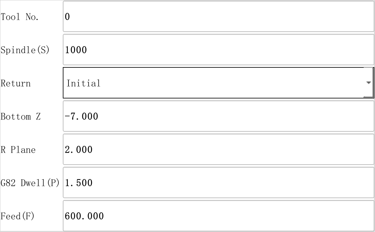
Click the screenshot to view the original image.
Figure 4: The extra input is the original
lineEdit_17, bound to#6009.item[#9048.version]. The postprocessor multiplies 1.5 by 1000 to output P1500.Change the same hole to G83. Enter 2 for G83 Peck(Q) and 0.5 for G83 Clear.
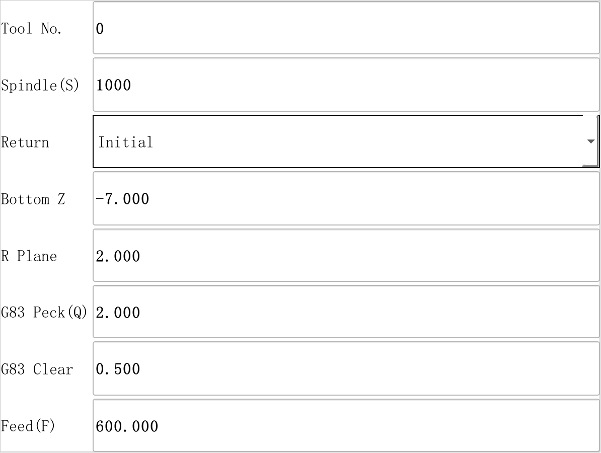
Click the screenshot to view the original image.
Figure 5: The original
lineEdit_18andlineEdit_19bind to the selected hole in#6010and#6011, producing Q2.000 and K0.500.After clicking Gen G-Code for each choice, this hole's drilling line is:
G98G81X40.000Y10.000Z-7.000R2.000F600.000
G98G82X40.000Y10.000Z-7.000R2.000P1500F600.000
G98G83X40.000Y10.000Z-7.000R2.000Q2.000K0.500F600.000
These lines compare three separate choices; they are not instructions to run three cycles consecutively on the same hole. See the complete G82 text and G83 text. The complete program in the next chapter returns to G81.
Generation resets
#9048.versionand#6001.channelto −1, hiding the upper-right parameter area. Click the target hole's Center again to continue editing; reimporting is unnecessary. The generation entry clears the selection, not the hole's settings.7. Selection, filtering and ordering are different operations
Checkmarks choose which holes to machine. The Select column binds to:
-T11(#6001itemmin[#6001itemversion%%]<<"NO."<<%%+1)The caption numbers the displayed rows, while the checkmark is written to the original hole. Clearing it does not delete the geometry or the hole's settings.
These controls use four items of
#6000. Keep their numeric choices aligned with the processing scripts when customizing the page:Item Control Current values #6000.item[0]comboBox, Sort By0=Y Scan, 1=X Scan, 2=Shortest, 3=Optimal, 4=None #6000.item[1]comboBox_3, Zigzag0=No, 1=Yes; used by scan ordering #6000.item[2]comboBox_2, Filter0= >, 1=>=, 2===, 3=<=, 4=<#6000.item[3]lineEdit, Filter Dia.Compared with the radius extracted from the title Changing a language-pack label changes its displayed text. Reordering choices also changes the numeric values written by the control, requiring corresponding changes where those values are interpreted. Renaming the third choice alone does not change its algorithm.
Filtering rewrites checkmarks in bulk. Choose
=and enter 2 in Filter Dia., then click Hole Filter. Because the implementation compares radii, the three radius-2 holes remain selected and the radius-3 hole is excluded. Every filter operation recalculates all checkmarks; it does not merely narrow the previous selection.Ordering chooses the processing sequence. For manual arrangement, select None under Sort By, then use Up, Down or Top. This example moves the original NO.2 to the top, then applies the filter above.
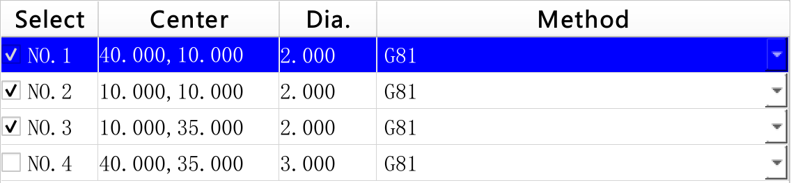
Click the screenshot to view the original image.
Figure 6: The first row is center 40,10 and retains its −7 depth. The displayed NO.1 now labels the first row, not necessarily the first circle originally imported.
Sort By choice Meaning Y Scan / X Scan Group and scan by the corresponding coordinate; Zigzag controls the direction of adjacent scan rows Shortest Choose successive holes by nearest-neighbor distance from the starting point Optimal Improve the nearest-neighbor route by exchanging path sections None Keep the incoming hole sequence; useful for learning manual ordering Shortest and Optimal are interface names, not guarantees of a globally shortest route. Top currently swaps the selected row with the first row; it does not shift every intervening row down.
Generation adds further ordering. The built-in operation collects selected holes first and applies the chosen strategy. JavaScript then orders output by increasing tool number. With different tools, the displayed manual order need not be the final NC order. Tasks also pass through string keys such as
drill0anddrill1; once numbers reach two digits, string ordering can affect same-tool tasks. If sequence matters, inspect the XY order in the generated code.8. Troubleshooting
Symptom First check Editing one hole leaves others unchanged These are per-hole inputs; saving defaults does not immediately update other holes Reimporting resets individual settings Import rebuilds them from #6002The upper-right inputs disappear after generation Generation cleared the current selection; click the hole's Center again without reimporting Diameter filtering selects unexpected holes The current comparison uses radius; check against a circle of known size Settings appear attached to the wrong hole after moving rows Resolve the original index through itemversionbefore addressing settingsA custom button acts on another row after graphical picking Check for an old #6001.channel; first find#9048.versionin theitemversionlistAn added description updates on table clicks but not on graphical picks Check for updates placed only in selectDrillItem; bind its display to the current hole indexReturn has a blank caption Select a hole, then refresh the original DXF page as described in section 5 of this chapter; save any existing program text first, since the refresh clears that text area Selection for machining, the current hole, row order and per-hole settings now have separate roles. Next, follow the original NO.2 depth of −7 into the settings string and the generated Z word.
Previous lesson: DXF page and import · Reading guide · Next lesson: DXF postprocessing
在线咨询 - Download
