
- Home
- About
- Products
Motion controller
CM600 RTCP 6-Axis Motion controll
CM300 R 3-Axis Motion controller
CM300 3-Axis Motion controller
- Download
- Support
- Applications
Secondary Development
Extension example: add G196 bore milling to DXF
Download the bilingual offline manual (ZIP, 16.7 MiB, original images and example attachments)
DXF topic: DXF page and import → Hole table and settings → DXF postprocessing → G196 bore-milling example
The DXF postprocessing chapter connects a selected hole to its generated NC line. This chapter uses that route to add an actual machining method: a new choice, a new input area, appended settings, JS output and an NC macro. It uses the same four-hole drawing.
This example adds a fourth choice, “G196 Circular Bore Milling,” to the existing DXF page. The accompanying files include parameter definitions, native UI, the generator and the O9196 machining macro. G81/G82/G83 remain available; the new branch handles method value 3.
Download the complete learning package · Complete NC macro · Complete generated program
DXF centers + per-hole settings
          ↓
Select G196 Circular Bore Milling; store method value 3
          ↓
Postprocessor writes G196X…Y…Z…R…D…I…Q…F…
          ↓
NC interpreter calls O9196, mills layers, retracts to R, then returns with M99
1. See the completed page and toolpath first
Click the screenshot to view the original image.
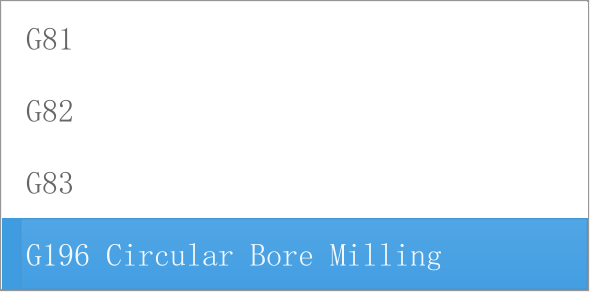
Figure 1. The four choices store values 0, 1, 2 and 3. G196 is the code assigned by this example, rather than a fourth drilling method supplied by the standard configuration.
Click the screenshot to view the original image.
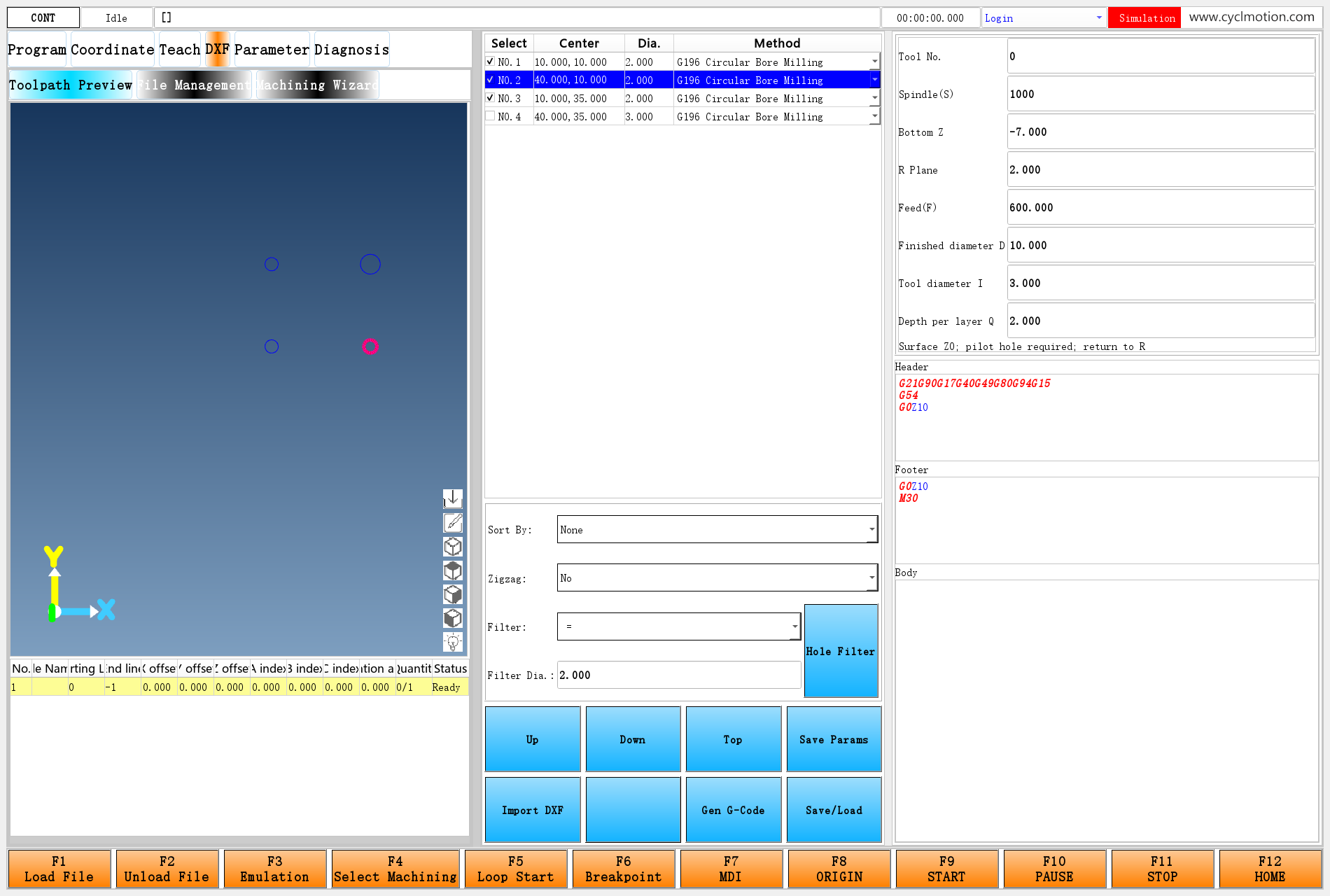
Figure 2. The example retains the hole table, center selection, filtering, Save Params and generation buttons. It adds one process area on the right. The second hole is selected.
Use the earlier four-hole DXF, select the three circles with radius 2, and enlarge existing pilot holes to diameter 10 with a diameter-3 tool. Before machining, each pilot hole must be at least as large as the tool and extend through the required machining depth. Set the workpiece surface to Z0. The three small circles can represent the positions of diameter-4 pilot holes. Leave the fourth circle unchecked.
The new Finished diameter D input determines the final diameter. It does not take its value directly from the table's Dia. column: that existing column stores a radius, which remains 2 here. The finished diameter is entered separately as 10.
Click the screenshot to view the original image.
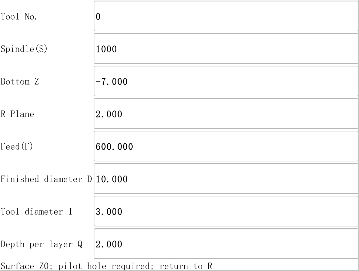
Figure 3. Tool No., Spindle(S), Bottom Z, R Plane and Feed(F) retain their existing fields. Finished diameter D, Tool diameter I and Depth per layer Q are added.
To reproduce the example:
- Install the files listed below in a learning copy of the application's runtime directory. Start that copy, follow the DXF enablement steps and import this chapter's four-hole drawing.
- Select the first hole and choose G196 Circular Bore Milling. Enter Tool No. 0, Spindle(S) 1000, Bottom Z −5, R Plane 2, Feed(F) 600, D10, I3 and Q2.
- Click Save Params, then import the same DXF again to apply these defaults to all four holes. Import rebuilds per-hole data, so make individual changes after this step.
- Select the second hole and change Bottom Z to −7. Leave the first and third at −5. Select None for sorting and apply the equality filter with value 2, as described in the hole-table chapter, to retain three checked holes.
- Use the following program header and use
G0Z10, thenM30, as the footer. Click Gen G-Code, then Save/Load, and save asdxf-g196-en.nc.
G21G90G17G40G49G80G94G15
G54
G0Z10
This example uses millimeters, the XY plane, absolute coordinates and feed per minute. Tool number 0 follows the existing postprocessor rule: it omits tool changing and G43 length compensation. Fit the tool and establish the work coordinates used by this example beforehand. R2 and the header's Z10 must clear the actual workpiece, fixtures and transfer paths. The displayed speed, feed and depth are teaching values; adapt them to the tool, material and machine.
Click the screenshot to view the original image.
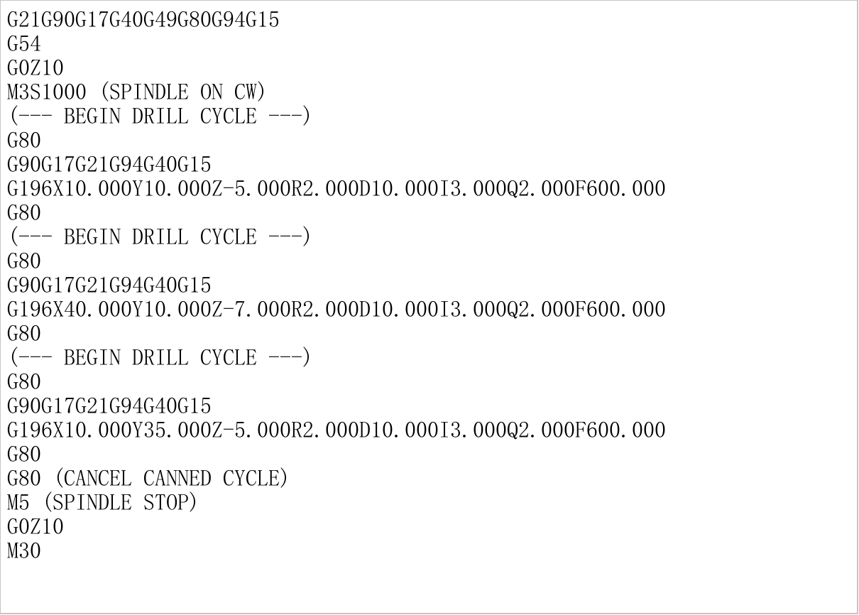
Figure 4. Each checked hole produces one G196 call. The second uses Z−7, the other two use Z−5, and the fourth produces no machining call.
The second-hole call is shown below. The complete program is linked at the start of this chapter.
G80
G90G17G21G94G40G15
G196X40.000Y10.000Z-7.000R2.000D10.000I3.000Q2.000F600.000
G80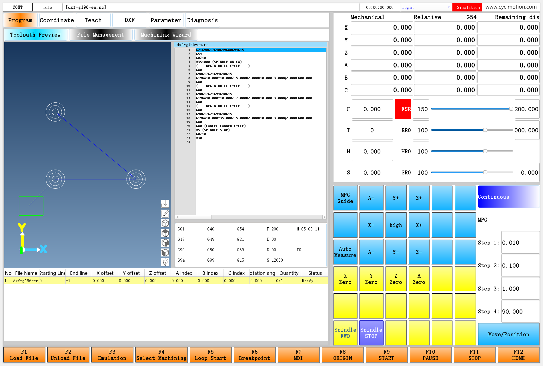
Click the screenshot to view the original image.
Figure 5. The original NC interpreter expands O9196 to produce this preview. White circles are tool-center paths; blue lines connect the holes. This is a path display, not a rendering of the finished bore walls. Circles at different Z levels overlap in this top view.
The second hole has cutting levels Z−2, −4, −6 and −7; its last step is only 1. The other holes use Z−2, −4 and −5. At every level, the outermost tool-center radius is
(10−3)/2=3.5. Adding the tool radius of 1.5 gives a finished bore radius of 5.2. Step 1: Connect the added files to the existing entry
The learning package follows the application's runtime layout, with
envandextScriptsat the same level. Close the learning copy, merge the package files into it, and keep the original files and parameter configuration for restoration. For an already customized project, merge the changes below into its files instead of replacing earlier customizations.File Purpose in this example env/dxfpageAdd parameter definitions, choices and current-language text before the existing page-loading logic env/dxf-custom/initA separate readable copy of those initialization statements; they are already included directly in dxfpage and need no second call env/dxf/dxf.uiAdd boreFramebeside the three existing process areas using native QLabel, QLineEdit and grid layoutenv/dxf/dxfloaderRetain import and assignment loops; select the first valid hole and refresh the hole table's choices env/dxf/generatecodeRetain field assembly; clear the old program and show a parameter message if generation returns empty text extScripts/processComplexVerticesMap.jsAdd buildCustomBoreand dispatch method 3 to it; keep other methods on their existing branchesenv/slib-dxf-custom.ncRegister O9196 and implement the G196 machining operation Confirm that G196, O9196 and
#6013–#6015are available in the target project. Initialization extends the original 10 fields to 13 while preserving the first ten. Re-entering the page does not reset saved D/I/Q defaults. On first extension, an unexpected field count or populated additional parameters produces an allocation-conflict message: merge those definitions first. If the project already has 13 fields, also confirm that its last three belong to this example.The new library file sits at the top level of
envand is registered at startup. After editing it, the main script can reload system libraries while NC is idle:widgetFunc["SysFunc","","ReloadSystemLib",""]This command registers the NC libraries. UI, parameter and postprocessor definitions still come from their respective files.
3. Step 2: Connect the choice, input area and per-hole parameters
Initialization statements in
dxfpagerun directly before its existing loading logic. Definitions therefore exist before controls are created; another interpreter is not started asynchronously to initialize them. The added wording follows#9980.item[2]for Chinese or English. Choose the interface language before entering the DXF page and importing the drawing.The Chinese choices are:
#6002.itemunit[0]="G81钻孔<<G82钻孔<<G83钻孔<<G196 圆插补扩孔"The English choices are:
#6002.itemunit[0]="G81<<G82<<G83<<G196 Circular Bore Milling"The existing import loop copies this text to
#6003.itemunit[p]. Choosing the fourth entry writes#6003.item[p]=3. G196 is the instruction number; 3 is the page's choice value.The added
boreFrameuses this visibility rule:-C(#9048version>=0&⍘version<#6001itemnum&ᝳitem[#9048version]==3) -V0#9048.versionremains the original hole index. Selecting a hole in the table or view drives the new inputs through that same index, without a separate selection mechanism.Added input Default and location Per-hole value Control name JS position Finished diameter D #6002.item[10]=10#6013.item[p]boreDiameterparts[11]Tool diameter I #6002.item[11]=3#6014.item[p]boreToolDiameterparts[12]Depth per layer Q #6002.item[12]=2#6015.item[p]boreStepparts[13]All three defaults use real-number type
itemtype=2and unit mm. For example, the finished-diameter input description is:-T(#6013item[#9048version]) -DThe original import script loops over
#6002.itemnum, allocates#[6003+field index]and copies defaults. Save Params copies the selected hole back to defaults using the same count. Generation also assembles fields using that count. Changing it from 10 to 13 carries the new data through all three paths, without adding a C++ parameter interface.G82 dwell and G83 peck/clearance retain their original positions. The new process uses neither those values nor the Return choice: it always returns to R. Switching back to G81/G82/G83 therefore preserves the meanings of the existing fields.
At the end of import, refresh only
entityTableso its choices are created from the new hole data. Destroying and recreating all ofdxfframeinside the Import DXF button's own event also destroys the button still handling that event. The whole-page refresh for standard Return choices remains the separate main-script operation described in the hole-table chapter, section 5.4. Step 3: Let JS write calls and NC perform motion
The complete generation function is included in the packaged postprocessor. The original
processDrillKeygains this dispatch at its beginning:if (key.split(":")[1] === "3") return buildCustomBore(key, outerArray);Appending D/I/Q after the original ten fields gives this shape for the second hole:
{
  "drill1:3:0:1000:0:-7:2:1:2:1:600:10:3:2": [
    [ { "x": 40, "y": 10, "z": 0 } ]
  ]
}
JS reads
parts[11..13], checksD>I>0, Q>0, F>0, Z<0, R>0, then writes G196 for each center. The existing outer processor continues to manage tool sorting, tool changes and spindle statements. Invalid settings clear the previous successful program; correct the settings and generate again.Keep G80 on a separate line before and after the custom call. The first cancels any existing canned cycle; the second cancels the custom instruction's retained mode. M99 restores the caller's G groups, so the macro's final G0 does not cancel G196 in the calling program. Do not combine
G80G196...on one line: the group containing G80 changes that line's dispatch route.5. Step 4: Understand the complete O9196 operation
The general extension mechanism maps G196 to
9000+196, or O9196. Its required argument positions are:Word O9196 local variable Flag for an explicit word on this line X, Y, Z #0,#1,#2#22,#23,#24R #9#31D #14#36I #6#28Q #13#35F #15#37A flag of 1 means the word was supplied on the current line. The macro also checks
#56=1for absolute coordinates,#57=1for the millimeter unit scale, and#58=17for the XY plane. Z is in#2and R in#9: do not copy G81's specialized argument positions or replace this G196 with an ordinary M98 call.After its entry checks, the complete macro copies inputs to
#60–#67and uses#68–#71for calculations, avoiding the general-extension arguments in#0–#58. Its cutting section follows. The entry checks and error exit are in the complete macro file.#60=#0 #61=#1 #62=#2 #63=#9 #64=#14 #65=#6 #66=#13 #67=#15 #68=[#64-#65]/2 #69=#65*0.4 #70=0 G80 G90G17G40G94G15 G0Z#63 G0X#60Y#61 G1Z0F#67 WHILE#70>#62DO1 #70=#70-#66 IF#70<#62THEN#70=#62 G1Z#70F#67 #71=0 WHILE#71<#68DO2 #71=#71+#69 IF#71>#68THEN#71=#68 G1X[#60+#71]Y#61F#67 G3X[#60+#71]Y#61I-#71J0 END2 G1X#60Y#61 END1 G0Z#63Focus on its two loops:
- The outer loop controls Z depth. Start at surface Z0, subtract Q per layer, and clamp the last step to the requested bottom. Return to the center after each layer, then descend inside the existing pilot hole to the next level.
- The inner loop controls expanding radius. The final tool-center radius is
(D−I)/2. This example increases the radius by0.4×tool diameter. For a diameter-3 tool, the circles have radii 1.2, 2.4 and 3.5. Clamp the last radial step to the final radius as well.
For each circle, move along X to its start and use G3 for one full revolution. After the outer loop, the tool is at the center and retracts to R. In the G196 call, I means tool diameter, as defined by this extension. Inside the G3 line, I means the center's X offset from the arc start, so it is
I-#71. Each instruction defines the meaning of its words.This deliberately simple operation uses concentric circles at discrete depths, a radial step fixed at 40% of the tool diameter, the supplied F throughout, and no separate finishing allowance. A further extension can expose radial stepover, finishing allowance or a separate plunge feed through the same parameter path. Revisit the pilot-hole requirements when changing the tool or entry method.
When inputs violate the contract, the macro writes a message to
#9997and sets#319.item[6]=1before any of its moves, preventing the following main-program motion from continuing. Normal and error paths share the final M99. Library structure scanning ends an O program at M99; do not put an intermediate M99 before an error branch that belongs to that same macro.6. Connecting the next process
Thread milling can append method 4 and another available extension G number. Retain hole locations, filtering and sorting, then add pitch, effective thread diameter, tool diameter, handedness and entry/exit settings. Connect them through defaults, per-hole inputs, the parameter string, JS and the NC macro. Pitch must not inherit G82's seconds-to-milliseconds conversion, and the new macro must implement the helical toolpath explicitly.
What carries forward is the connection from existing page → per-hole settings → generated call → NC operation. Complete the next single-hole macro before connecting it to DXF batch generation.
7. Troubleshooting
Symptom First check A new drilling type does not show its parameter area Check the value written to #6003.item[p]and whether the area's condition uses the same original hole indexA new choice has a name but generates no machining line Check JS dispatch for stored method value 3; appending a caption does not add an output rule Generated G196 reports that its O program cannot be found Check O9196, duplicate definitions, the top-level slib file location, and library registration after changes A custom G code reads the wrong depth or diameter Use the general extension argument table and check appended setting positions; canned-cycle and ordinary M98 argument mappings differ For another process, define the single-hole program and its inputs first, then connect the choice, per-hole settings and postprocessor. Compare the complete files in the learning package to locate each change.
Previous: DXF postprocessing · Reading guide · Next: separate Normal Following page
Online - Download
