
- Home
- About
- Products
Motion controller
CM600 RTCP 6-Axis Motion controll
CM300 R 3-Axis Motion controller
CM300 3-Axis Motion controller
- Download
- Support
- Applications
Secondary Development
Extension example: add a separate Normal Following page to DXF
Download the bilingual offline manual (ZIP, 16.7 MiB, original images and example attachments)
Chapter 22 added G196 bore milling to the drilling page. This chapter keeps those files and adds a separate Normal Following page. X and Y move along a 2D contour while C changes its angle with the contour direction. G81, G82, G83 and G196 remain on the Drilling / Bore Milling page, together with the hole table, individual settings, filtering, sorting, header/footer editors, generation and Save/Load.
The example connects the existing
dxfContourInit,dxfContourand contour branch inprocessComplexVerticesMap.js. The work is to organize pages, define parameters, bind widgets, and write import and generation scripts. It requires no C++ changes and no replacement for the existing normal-following algorithm.Download the combined Chapter 22/23 learning package · Example contour drawing · Complete generated program
1. What the completed example provides
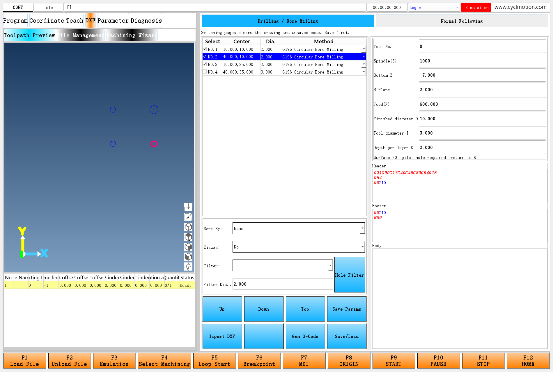
Click the screenshot to view the original image.
Figure 1. The main-screen DXF entry stays in its original position. Drilling / Bore Milling and Normal Following are added above the existing hole table and G196 settings.
Each page has its own UI file. Switching replaces the content below the two selectors. Both pages continue to use the native drawing area on the left.
Function Drilling / Bore Milling Normal Following Data taken from the drawing Hole positions, such as circle centers Connected 2D contours Table contents Hole positions, methods and individual settings Use checkbox, start and end Settings storage Chapter 22 per-hole parameters and #6002defaultsNew #6022; checked contours share these settingsGeneration entry dxfDrilldxfContourOutput G81/G82/G83/G196 X/Y/Z/C program made from G0 and G1 moves Switching pages clears the current drawing and unsaved program, so import the DXF again on the destination page. The two sets of default process settings are retained separately. The software has one current DXF entity collection, and both initialization functions use
#6001. Separate UI files therefore also need an explicit rule for sharing this data, explained in Section 6.2. Prepare the files and retain Chapter 22
Copy the application runtime directory to make a learning project. Close that copy of the application, then merge
package/envandpackage/extScriptsfrom the ZIP into it. Restart the learning copy, set#929.item[12]to 1 in the macro-parameter window, and open DXF. See DXF page and import for the enablement steps.Merge changes into a project that already has customizations. In particular, keep the Chapter 22 version of
processComplexVerticesMap.js, which includes the G196 branch, together with any other changes you have made. Do not replace it with the earlier version containing only three drilling methods.File or directory Treatment in this chapter Purpose env/dxfpageRetain Chapter 22 initialization; load the new page container Main DXF entry env/dxf/dxf.uiKeep the Chapter 22 file unchanged Drilling / Bore Milling page env/dxf/dxfloader,generatecodeKeep the Chapter 22 files unchanged Existing drilling import and generation env/slib-dxf-custom.ncKeep unchanged O9196 for G196 extScripts/processComplexVerticesMap.jsKeep the Chapter 22 file unchanged Three drilling methods, G196 and the existing contour branch env/dxf-normal/workbench.uiAdd Two selectors and a child-page frame env/dxf-normal/normal.uiAdd Contour table, settings, code editor and buttons env/dxf-normal/switch-pageAdd Clear shared data and switch pages env/dxf-normal/import-contoursAdd Import, recognize contours and initialize the table env/dxf-normal/generateAdd Check settings and generate the complete program env/dxf-normal/save-loadAdd Save the file and load the program page env/dxf-normal/empty.dxfAdd Empty drawing used to clear internal DXF data on a page switch env/dxf-normal/initis a readable reference copy of the initialization already included directly indxfpage; do not add another startup call. Chapter 22'senv/dxf-custom/initis also retained as a reference file.The example uses
#6020–#6022. Check that these numbers are available in an existing project. Also retain Chapter 22's allocation of#6013–#6015and G196/O9196. The new numbers are not permanently reserved by the software. If they conflict, change their references consistently in the scripts and UI files.3. Decide the machining conventions first
This page generates millimetre programs in the G54 XY plane, with the workpiece surface at Z0. X/Y describe the contour, Z controls retraction and cutting depth, and C controls direction.
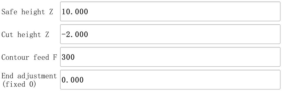
Input field Parameter Example Effect on the program Safe height Z #6022.item[0]10 Retract to Z10 before each section and at program end Cut height Z #6022.item[1]−2 Feed down to Z−2 after positioning Contour feed F #6022.item[2]300 Output F300 on the plunge; later contour moves retain it End adjustment (fixed 0) #6022.item[3]0 Keep the original contour length; read-only in this example The program follows one contour layer at a fixed Z. It does not generate multiple depth passes, tool changes, spindle starts or G43 length compensation. Fit the appropriate tool, establish the work coordinates, and arrange spindle or other tool actions for the intended process. The safe height must clear the workpiece and fixtures throughout repositioning.
C uses the existing JavaScript convention:
C = contour tangent angle − 90°Motion along +X gives C−90°; motion along +Y gives C0°. This selects the right-hand normal relative to travel. It does not automatically identify the inside or outside of a closed contour. The mechanical C zero, positive direction, permitted angles and actual axis mapping must match the convention. Displaying the C coordinate row and configuring its physical drive are separate tasks; see Axis configuration.
4. Define page selection, page paths and process settings
Separate the data by purpose before binding the widgets. Do not place the four contour fields into the drilling page's ten-field or thirteen-field process string.
Parameter field Use in this example #6020Current page: 0 for drilling/bore milling, 1 for normal following #6020.versionPage requested by the latest selector click #6020.descriptionInitialization marker DXF_NORMAL_V1#6020.itemtitle[0–19]Page names, buttons, column headings and messages #6021.itemdesc[0]Current child UI file path #6021.channelField used by the child-frame layout; set to 0 here #6022.item[0–3]Four process values #6022.itemtitle[0–3],itemtype,itemunitInput names, types and units #6022.descriptionImported file path #6022.unitReused as the page's status message #6022.itemdesc[0]Complete generated NC text #6022.itemdesc[1]Four process values joined into a string #6022.permission,#6022.channelGeneration loop index and checked-contour count The last entries describe this example's use of those fields. Their names do not make them login permissions or an NC interpreter channel. The core initialization is shown below; see init for the full script.
#6020.itemnum=20
#6021.itemnum=1
#6022.itemnum=4
#6020.description="DXF_NORMAL_V1"
#6022.item[0]=10
#6022.item[1]=-2
#6022.item[2]=300
#6022.item[3]=0
#6022.itemtype[0]=2
#6022.itemtype[1]=2
#6022.itemtype[2]=1
#6022.itemtype[3]=2
Type 2 is used for real numbers and type 1 for integers. The complete initialization supplies the defaults only on first use. Reopening DXF therefore does not overwrite values just entered. An existing example marker preserves the current settings; on first installation, an existing item collection in any of the three parameters produces an allocation-conflict message.
Chinese and English names are defined here too. The script assigns Chinese text first, then assigns English text when
#9980.item[2]==1. Both UI editions refer to the same parameter fields. Script filenames and widget object names remain unchanged.5. Build the page container, then the separate page
The main interface's existing
dxfframeloads DXF through#899. Keep that entry and change the UI it loads to:#899.itemdesc[0]="/env/dxf-normal/workbench.ui" widgetFunc["QFrame","dxfframe","refresh",""]In Qt Designer, create the following structure. Object names must match the scripts; layouts allow the page to resize with the window.
workbench.ui
└─ Vertical layout
   ├─ dxfNavigation: horizontal layout
   │  ├─ drillTab: QLabel, Drilling / Bore Milling
   │  └─ normalTab: QLabel, Normal Following
   ├─ switchNotice: QLabel, switching message
   └─ dxfContent: QFrame, current child page
Set the
accessibleDescriptionofdxfContentto:-T(6021)Initialization sets
#6021.itemdesc[0]="/env/dxf/dxf.ui", so the first page is still Chapter 22's page. Selecting the other page changes the path to/env/dxf-normal/normal.uiand refreshesdxfContent.The complete binding for the Normal Following label,
normalTab, is:-T(#6020itemtitle1) -A:(clickedEvent:/env/dxf-normal/switch-page[0](#6020version=1)) -C1(#6020==1) -C0(1) -DThe first line reads the text. Clicking assigns requested page 1 and calls the switch script. The two conditions choose selected/unselected styles;
-Dupdates the display from the parameters. The Drilling / Bore Milling selector uses 0 instead.Keep both selectors outside
dxfContent. Refreshing a QFrame destroys its old child widgets and creates the new page. Keeping navigation in the outer container leaves a way back and avoids destroying the button handling the current click.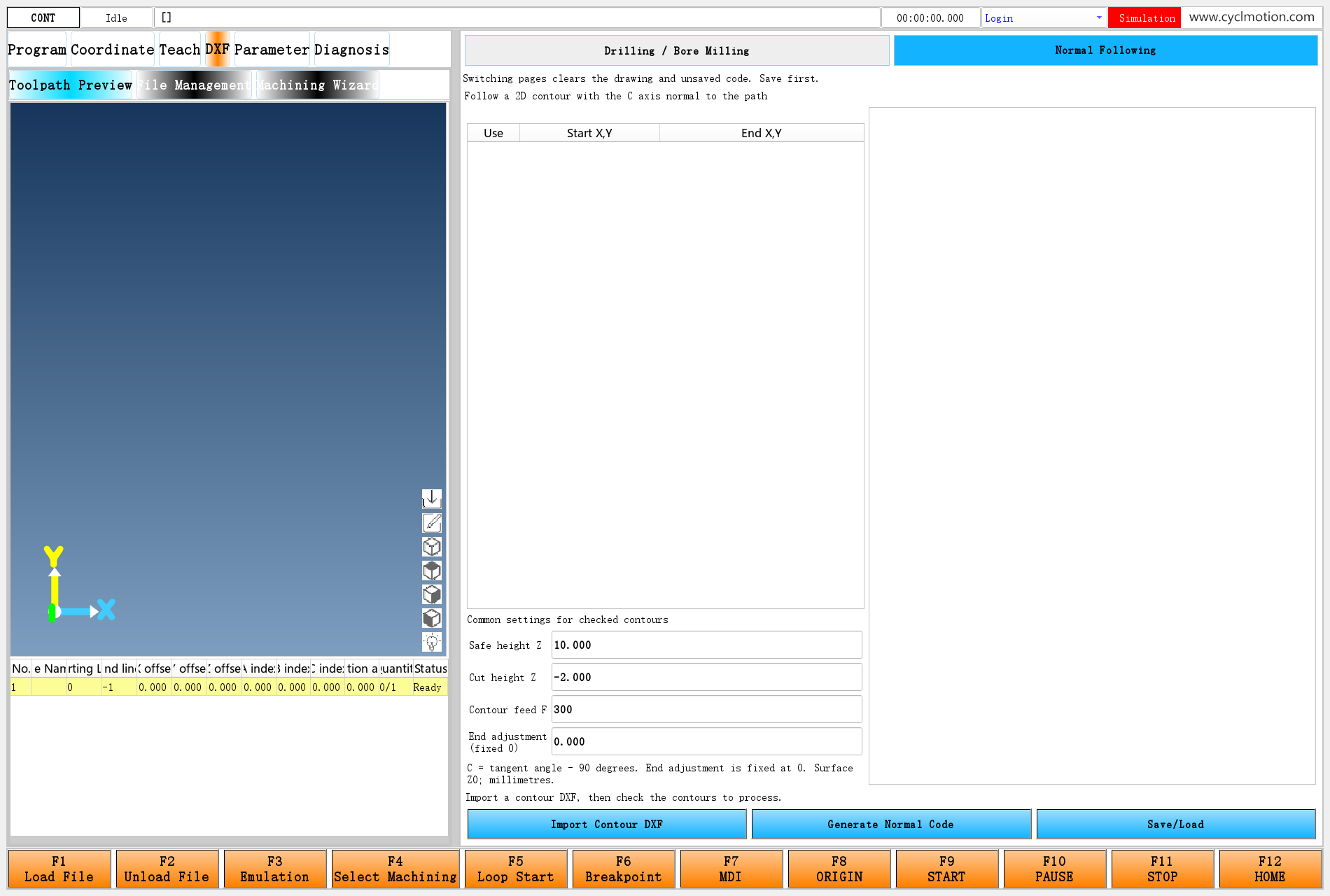
Click the screenshot to view the original image.
Figure 2. The new page after switching. Its empty table and drawing area indicate that no contour file has been imported on this page. The drilling page still exists.
Build
normal.uiusing the existing DXF styles and widget types. Its main objects are:Object name Qt widget Purpose normalTableQTableWidget Three-column contour table normalSafe,normalCut,normalFeed,normalEndQLineEdit Four process values; the last is read-only normalBodyQPlainTextEdit Display and edit generated code normalImportQPushButton Import Contour DXF normalGenerateQPushButton Generate Normal Code normalLoadQPushButton Save/Load normalSource,normalStatusQLabel File path and status message For example, Safe height Z uses
-T(#6022item0)and-D. The status label uses-T(#6022unit)and-D. See the complete normal.ui.6. Deal with shared DXF data before switching pages
The switching script first checks whether the destination differs, then checks machining and pause status. When switching is allowed, its core sequence is:
widgetFunc["readDxf","env/dxf-normal/empty.dxf","",0] #6001.itemnum=0 #6001.channel=-1 #9048.version=-1 #6022.description="" #6022.itemdesc[0]="" #6022.unit=#6020.itemtitle[11] #6020=#6020.version #6021.itemdesc[0]="/env/dxf/dxf.ui" IF#6020==0GOTO10 #6021.itemdesc[0]="/env/dxf-normal/normal.ui" N10 widgetFunc["QFrame","dxfContent","refresh",""]readDxfclears the old drawing and internal DXF entities. Reading a valid DXF with no entities makes the internal geometry agree with the empty table. Setting only#6001.itemnumto zero would not do this.The script then clears selection, filename and old output before changing the child path and refreshing the frame. It leaves the drilling defaults in
#6002and normal-following values in#6022.item[0–3]intact. See switch-page for the full script.This is a useful rule for multi-page customization: separate pages do not necessarily have separate internal data. When reusing shared software data, define when it is imported, cleared and consumed.
7. Import DXF with contour initialization
The new import button uses this binding. It is a native QPushButton, and the script runs on
MouseButtonRelease.-T(#6020itemtitle7) -A:(MouseButtonRelease:/env/dxf-normal/import-contours[0]) -C(#319item3==1||#319item7==1) -E0 -DFollowing the existing configuration pattern, the button is disabled while machining is busy or paused. After a file is selected, the important script statements are:
IFwidgetFunc["readDxf",#100,"",0]!=0GOTO90 #6022.itemdesc[1]=#6022.item[0]+":"+#6022.item[1]+":"+#6022.item[2]+":"+#6022.item[3] widgetFunc["dxfContourInit","","","\""+#6022.itemdesc[1]+"\""] IF#6001.itemnum==0GOTO90 #6022.description=#100 #6022.unit=#6020.itemtitle[10] #9048.version=0 #6001.channel=0 widgetFunc["QTableWidget","normalTable","refresh",0]readDxfreads entities.dxfContourInitrecognizes connected contours and creates#6001. The drilling page usesdxfDrillInitat this point. Changing the function name alone is insufficient: the table and settings string must match contour data too.Pass the four settings in this order:
SafeZ:CutZ:Feed:EndAdjustment
10:-2:300:0
The actual string can contain trailing zeros, such as
10.0000:-2.000:300:0.000; its meaning is the same.dxfContourInitparses the fourth argument as a text expression, so the script adds a double quote at each end of the entire settings string. Do not omit that extra quoting by assuming the call behaves exactly like drilling initialization.Canceling the file dialog retains current content. Old output is cleared only after a new file has been selected. A read failure or an empty contour result clears the table and displays a message. See import-contours for the full script.
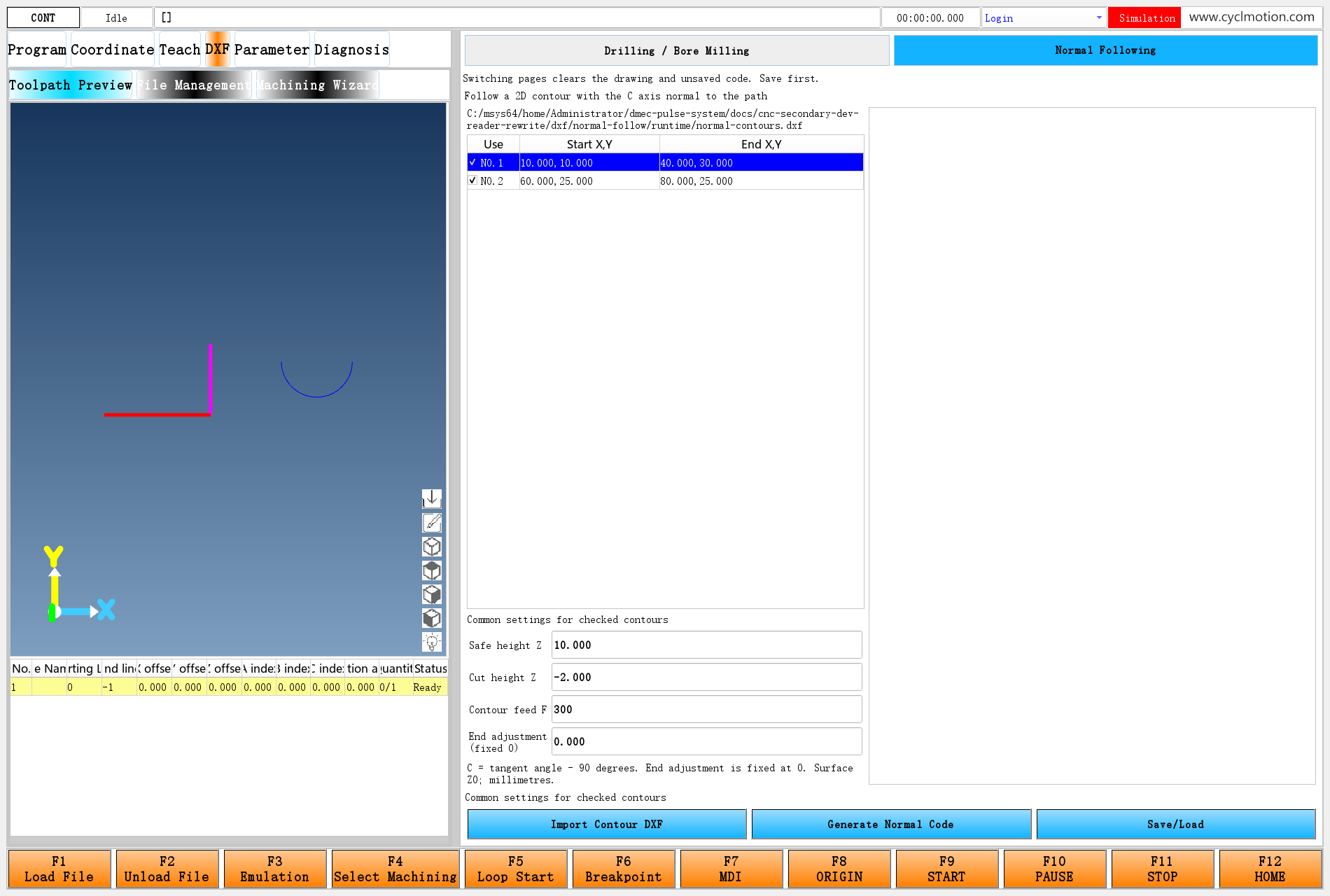
Click the screenshot to view the original image.
Figure 3. Three drawing entities produce two contours: two connected lines form the L shape; one arc forms the other contour. Entity count and contour count need not be equal.
The example contains lines
(10,10)→(40,10)and(40,10)→(40,30), plus an arc centered at(70,25), radius 10, from 180° to 360°. All are on layerNORMAL.The current initializer joins geometry by layer. Its built-in call uses connection tolerance 0.001 and angular sampling steps of 1° for arcs and circles. This page does not add controls for those three values. Check drawing units, endpoint connections and layers; visually touching lines on different layers must not be assumed to form one contour.
8. Connect the contour table to the drawing

Click the screenshot to view the original image.
Figure 4. Start and end identify the source contour. The Use checkbox decides whether to generate machining code; the blue row identifies the object currently being inspected.
After initialization, the fields mean:
Field Meaning #6001.itemnumContour count #6001.itemtitle[p]Text in the form contour(start)->(end)#6001.itemmin[p]Include in generation: 1 means checked #6001.itemdesc[p]Four process values for this contour #6001.itemversion[row]Original contour index for a table row #9048.versionOriginal index highlighted in the drawing #6001.channelCurrent table row Reuse Chapter 20's table technique for the checkbox and row number:
-T11(#6001itemmin[#6001itemversion%%]<<"NO."<<%%+1) -C1(#9048version==#6001itemversion%%) -C0(1) -D%%is the current row. Read the original index throughitemversion, then read or write the checkbox for that object. Displayed NO.1 corresponds to internal index 0.The start column extracts the text inside the first pair of parentheses:
-参数(#6001itemtitle[#6001itemversion%%]*")"/"(")
-事件:(clickedEvent:/env/dxf/selectDrillItem[1](#9048version=#6001itemversion%%<<#6001channel=%%))
-C1(#9048version==#6001itemversion%%)
-C0(1)
-D
These are the literal attribute keywords used in the UI file, including
-参数and-事件; keep them when copying the binding. The end column first skips->, then extracts the parenthesized coordinates. Clicking a coordinate cell assigns the selected original index and row. This example reuses the existing emptyselectDrillItemevent script: the two assignments in its event parameters perform the selection.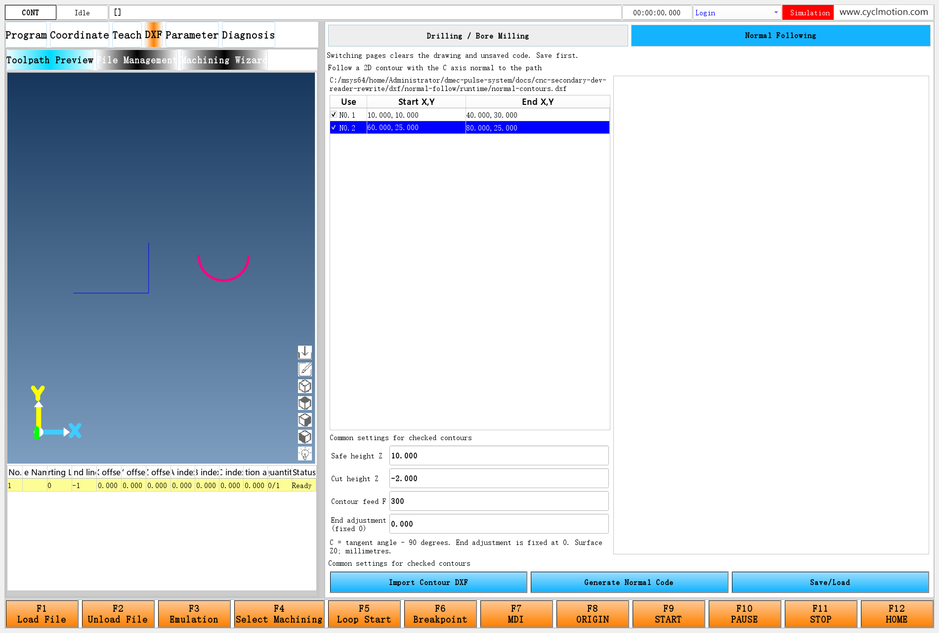
Click the screenshot to view the original image.
Figure 5. Clicking the second row's coordinates selects the semicircle for inspection. Both rows remain checked, so both are still included in generation.
Inspection selection and machining inclusion are different. Selecting a row does not exclude other checked contours. To generate only the L shape, clear Use in the second row.
The new page keeps the table in import order. The internal generation function rearranges contours and changes
itemversion, so the script restores0,1,2…before and after generation. This keeps subsequent checkbox actions and repeated generation tied to the source objects. The listed endpoints identify the imported contour; they need not be the generated start and end because internal ordering can reverse a contour.9. Bind the inputs and apply settings to the contours
Click the screenshot to view the original image.
Figure 6. All checked contours share these settings. After editing a value, click Generate Normal Code to rebuild the program.
The drilling page allows individual hole settings. This page instead loops over
#6001at generation time and writes the same four-field string to everyitemdesc. Changing Cut height Z to −3 and Contour feed F to 450 after importing therefore affects every generated section; reimporting is unnecessary.End adjustment is fixed at zero because of how the existing postprocessor works. A nonzero adjustment extends or trims the XY endpoint but does not recalculate C at the modified endpoint. Zero preserves the original contour and angle relationship taught here. Opening this setting to the user later also requires endpoint-angle handling.
Four checks precede generation: Safe Z must be at least 0.001, Cut Z at most −0.001, feed at least 1, and end adjustment exactly 0. These checks fit the example's Z0 surface convention and avoid the existing JavaScript rule
parseFloat(value) || defaultValue, which substitutes a default for zero.10. Implement the generation button
The button runs
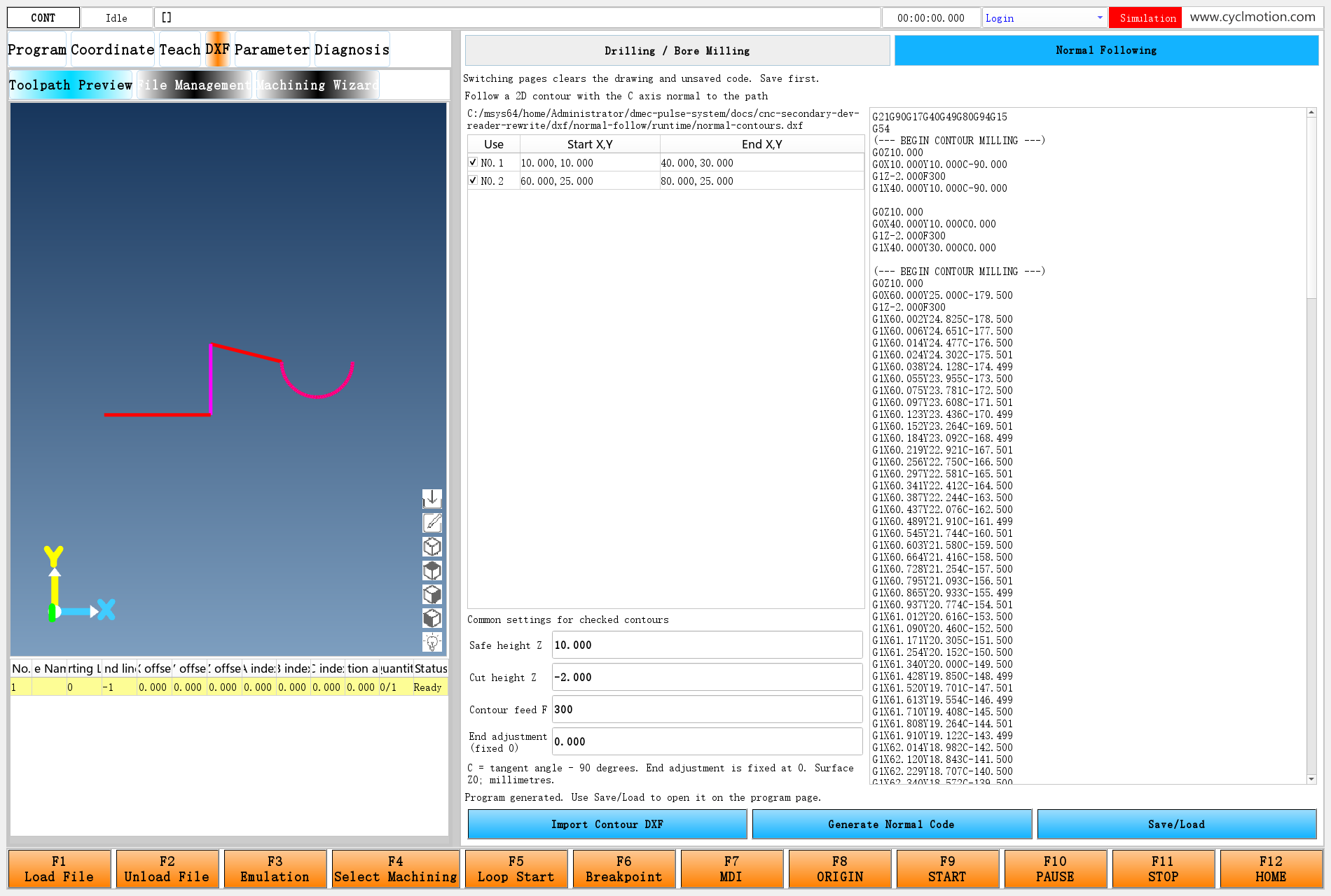
env/dxf-normal/generate. Its sequence is: clear old output → check settings and inclusion → assign contour settings → call built-in generation → restore table indices → add a header → display the text.Here is the complete generation script from the learning package. Read each block by purpose before following its individual statements.
IF#6020!=1GOTO99
#6022.itemdesc[0]=""
widgetFunc["PlainTextEdit","normalBody","clear",""]
IF#6001.itemnum==0GOTO90
IF#6022.item[0]<0.001GOTO91
IF#6022.item[1]>-0.001GOTO91
IF#6022.item[2]<1GOTO91
IF#6022.item[3]!=0GOTO91
#6022.itemdesc[1]=#6022.item[0]+":"+#6022.item[1]+":"+#6022.item[2]+":"+#6022.item[3]
#6022.permission=0
#6022.channel=0
WHILE#6022.permission<#6001.itemnumDO1
#6001.itemversion[#6022.permission]=#6022.permission
#6001.itemdesc[#6022.permission]=#6022.itemdesc[1]
IF#6001.itemmin[#6022.permission]==1THEN#6022.channel=#6022.channel+1
#6022.permission=#6022.permission+1
END1
IF#6022.channel==0GOTO90
#6022.itemdesc[0]=widgetFunc["dxfContour","","",0]
; This page presents source contour order; generation may change itemversion.
#6022.permission=0
WHILE#6022.permission<#6001.itemnumDO2
#6001.itemversion[#6022.permission]=#6022.permission
#6022.permission=#6022.permission+1
END2
widgetFunc["QTableWidget","normalTable","refresh",0]
IF#6022.itemdesc[0]==""GOTO92
#6022.itemdesc[0]="G21G90G17G40G49G80G94G15\nG54\n"+#6022.itemdesc[0]
widgetFunc["PlainTextEdit","normalBody","insertText",#6022.itemdesc[0]]
#6022.unit=#6020.itemtitle[12]
GOTO99
N90
#6022.unit=#6020.itemtitle[14]
GOTO93
N91
#6022.unit=#6020.itemtitle[13]
GOTO93
N92
#6022.unit=#6020.itemtitle[16]
N93
widgetFunc["messageBox",#6020.itemtitle[1],#6022.unit,""]
N99
Three details matter here:
- Clear old output first. If nothing is checked or settings are invalid, the code area is cleared and a message appears. The previous successful result cannot be mistaken for a new result.
- Count checked contours. Two table rows do not mean two active contours; the blue inspection row does not determine how many contours are included.
- Add only the header. The existing contour postprocessor already ends with a safe retract and M30. Do not append the drilling page's footer again.
Click the screenshot to view the original image.
Figure 7. The header explicitly selects G21/G90/G17/G94 and G54. Connecting lines help inspect the contour sequence; the NC text determines the actual retract, positioning and plunge moves.
11. Understand the existing angle and JavaScript mechanism
Follow four transformations:
readDxf
  Drawing entities
    ↓ dxfContourInit
  Connected contours + #6001 table + four process values
    ↓ dxfContour
  Checked contours → choose order/direction → split at direction changes
    ↓ splitPointsByAngleChange
  Point x/y: position; point z: temporary storage for tangent angle
    ↓ processComplexVerticesMap.js / processNonDrillKey
  C=z−90; cutting Z comes from the process string
The existing calculation evaluates
atan2(ΔY,ΔX)between adjacent XY points and converts the result to degrees. Adjacent direction differences are reduced to(-180°,180°]and accumulated, allowing angles to continue across ±180°. A direction change greater than 10° creates a new section. The corner point belongs to both the end of the old section and the start of the next.The following simplified data illustrates the L shape as one contour split into two directional sections:
// Illustration of the data meaning. The software supplies this object;
// the page does not construct it manually.
dataMap = {
  "contour0:10:-2:300:0": [
    [{x:10, y:10, z:0},  {x:40, y:10, z:0}],
    [{x:40, y:10, z:90}, {x:40, y:30, z:90}]
  ]
};
outputFlag = "GCode";
Point z represents an angle here, not cutting depth.
processNonDrillKeycopies the point withz-90and writes that value as C. Z−2 comes from the second process value in the key. Writing the point's z as machine Z would break the data convention.This is why the chapter needs no second postprocessor file. Chapter 22's JavaScript still handles hole keys beginning with
drill…; contour keys enter the existing contour branch. The independent page chooses the built-in entry and therefore the type of data sent to JavaScript.This page adds no machining-order editor. The built-in function sorts contours and can reverse them; the result then passes through string-key storage and JavaScript task traversal. With many contours, especially two-digit indices, do not treat the table order as the final machining order. Strict ordering requires additional index/key and postprocessor sorting rules, followed by inspection of the complete output.
12. Inspect the corner: retract, rotate, then continue
Click the screenshot to view the original image.
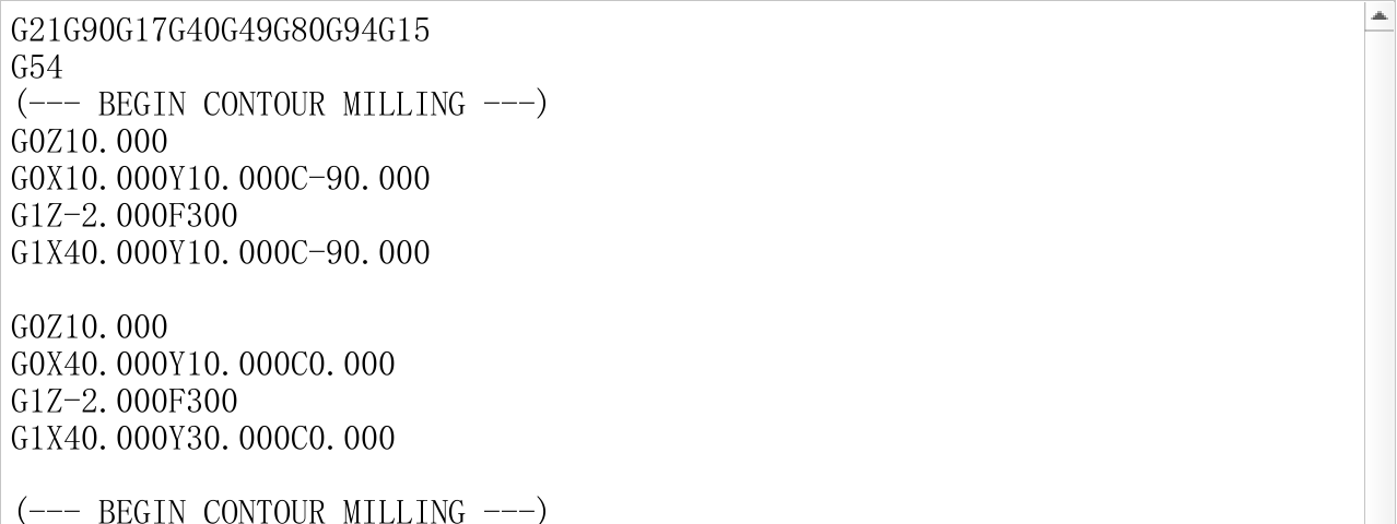
Figure 8. The first section uses C−90 and the second uses C0. The tool has retracted to Z10 before C turns.
The relevant generated code is:
G0Z10.000
G0X10.000Y10.000C-90.000
G1Z-2.000F300
G1X40.000Y10.000C-90.000

G0Z10.000
G0X40.000Y10.000C0.000
G1Z-2.000F300
G1X40.000Y30.000C0.000
The first section travels along +X from
(10,10)to(40,10), holding C−90°. The right angle exceeds the built-in 10° split threshold, ending that section. The next section retracts, turns C to 0° at the same XY location, plunges again and travels along +Y to(40,30).This does not rotate continuously at cutting depth through a sharp corner. Processes requiring uninterrupted cutting, rounded transitions or special corner actions need an additional process design. Repositioning commands contain X/Y/C together: transfers between contours position them together at safe Z. This example does not add a separate “rotate C first, then move XY” action.
13. Inspect the arc: C changes while XY changes
Click the screenshot to view the original image.
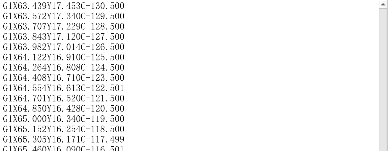
Figure 9. The arc has been sampled into short straight moves. C changes continuously with the sampled points.
The beginning of the semicircle is:
G0Z10.000
G0X60.000Y25.000C-179.500
G1Z-2.000F300
G1X60.002Y24.825C-178.500
G1X60.006Y24.651C-177.500
G1X60.014Y24.477C-176.500
The output is a list of
G1X…Y…C…points, rather than G2/G3 arc commands. Arc points are sampled at 1° intervals, and their adjacent points determine direction. C therefore follows the sampled segment directions. The initial −179.5° and small variations in the final decimal places follow from this calculation; do not simply replace them with whole degrees.The smooth section does not repeatedly retract as the sharp corner does. The algorithm also does not automatically confine accumulated C to −180° through 180°; a complete circle can continue accumulating angle. Applying a per-line modulo operation for tidy numbers can introduce an unwanted reversal at the boundary. Rotary travel, rotation direction and cable limits belong in the machine-specific process design.
14. Save/load and inspect the native toolpath preview
Save/Load reuses the application's file-saving and program-loading approach, reading from this page's
normalBody. If you edit the code area, the current visible text is what gets saved.The sequence is: read text → reject empty text → choose an NC filename →
savefile→ update the#334machining list,#9047displayed file and#403machining file → set#810.permissionto 0 to return to the program page. See save-load.#6022.itemdesc[0]=widgetFunc["PlainTextEdit","normalBody","plainText",0] IF#6022.itemdesc[0]==""GOTO90 #100="" widgetFunc["saveFileName","*.nc","",100] IF#100==""GOTO1 widgetFunc["savefile",#100,"",#6022.itemdesc[0]]Saving does not automatically start machining or simulation on this page. Save the example as
dxf-normal-en.nc, inspect it under Program → Toolpath Preview, then use Emulation in the existing function-key area (F3 in the screenshot) to preview it.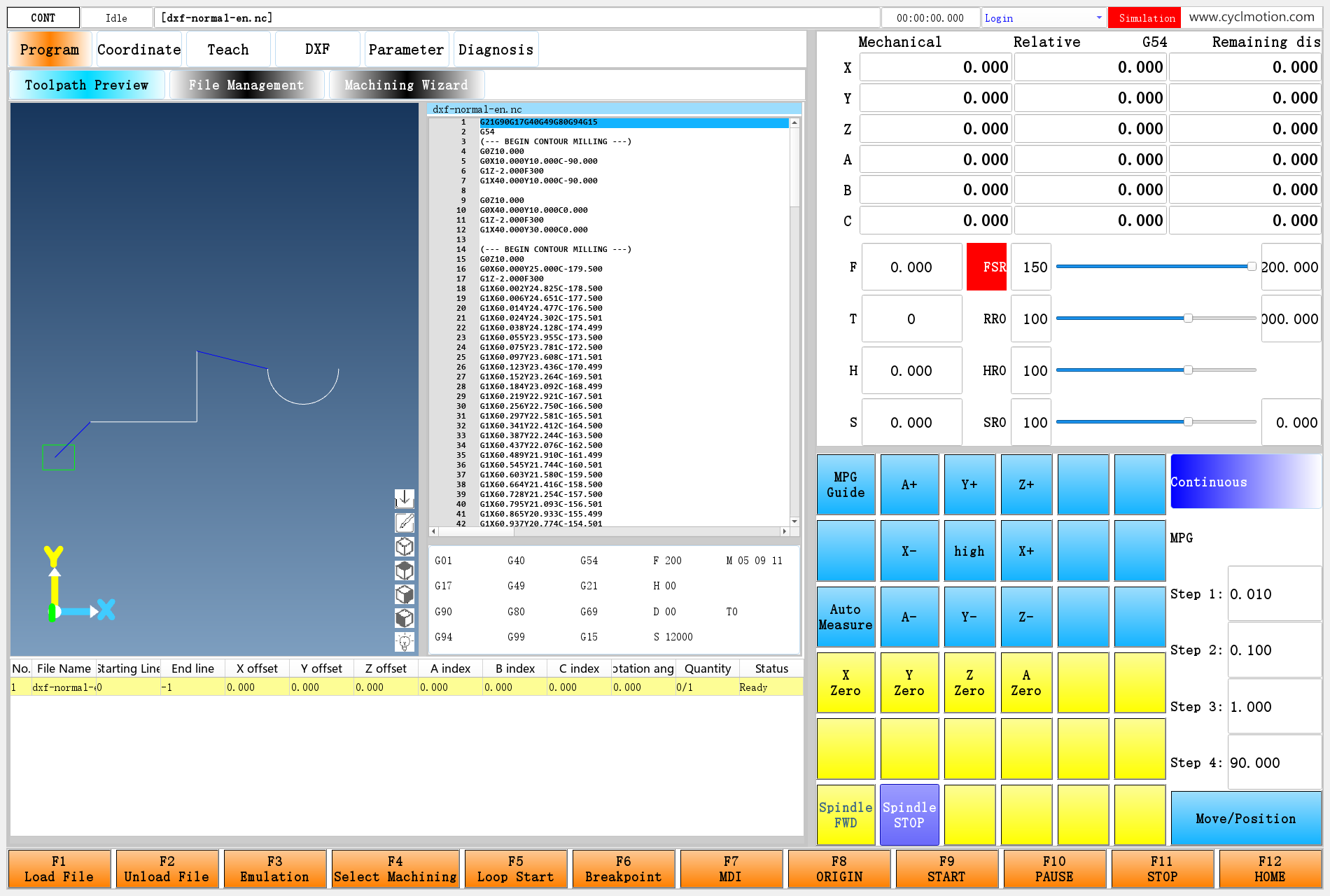
Click the screenshot to view the original image.
Figure 10. The left area shows the L shape, semicircle and positioning connections. The editor includes C words, and the top status indicates simulation. XY lines show position; inspect C in the code as well. Ordinary toolpath lines do not represent an oriented tool model.
Choose the track view and top view, then adjust zoom. In the tool-following view, the image follows the tool position. If the tool is at the origin and the drawing is away from it, some contours may lie outside the visible area.
15. Return to drilling and keep using its functions
Click the screenshot to view the original image.
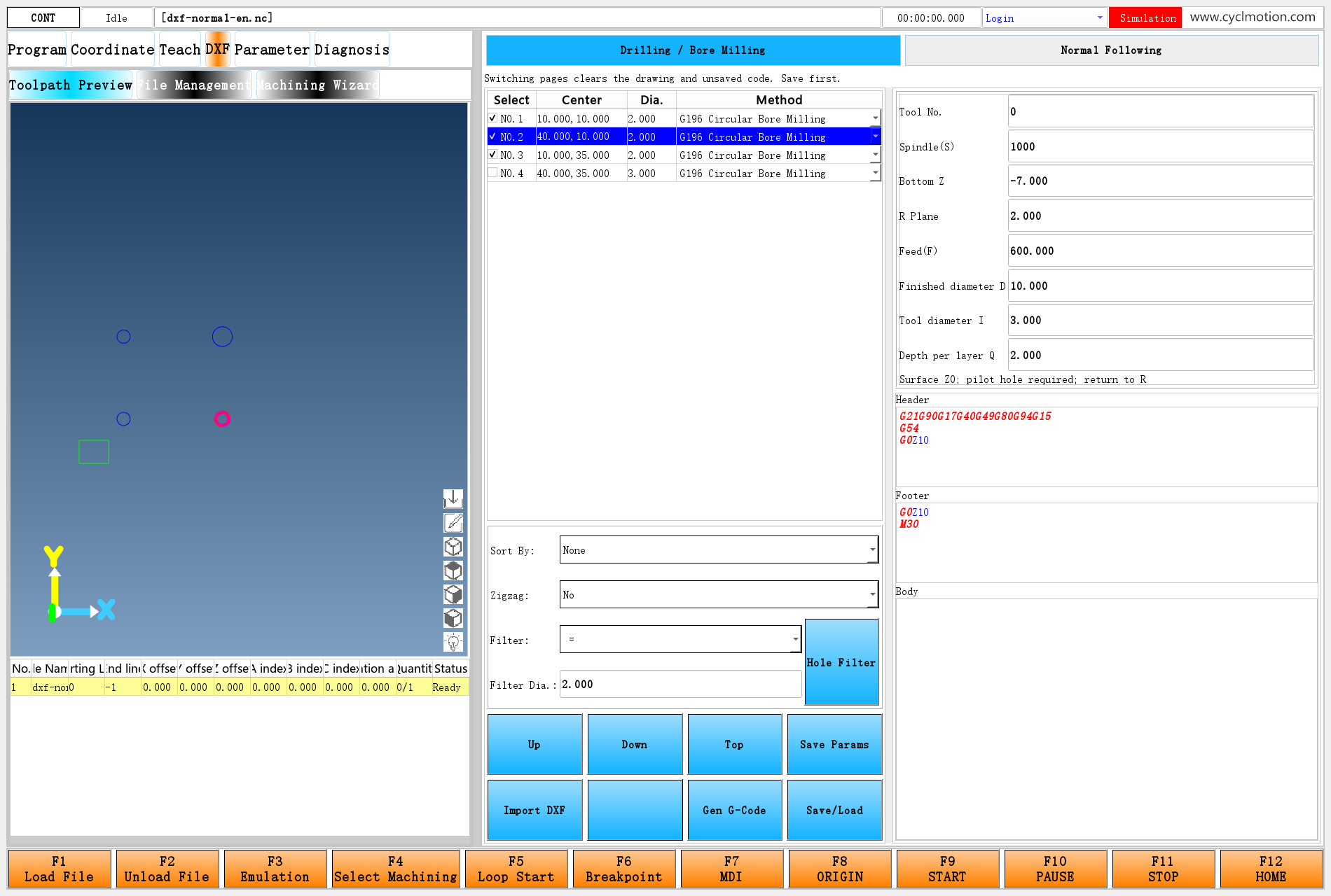
Figure 11. Reimport the four-hole drawing on the Chapter 22 page. G196 and D/I/Q remain available, as do G81, G82 and G83 in the original method list.
What is retained is the existing functionality and default settings, rather than unsaved edits to individual holes from before the switch. Reimporting rebuilds hole data. For example, set Chapter 22's second-hole Z−7 again after importing. Also check the header and footer before saving.
If only the normal page remains, check that
workbench.uistill contains both selectors. If G196 disappears, check whether an older UI or JavaScript replaced the Chapter 22 version. If the drilling page still shows contour endpoints, check that the switch script changes#6021.itemdesc[0]and refreshesdxfContent.16. Extend the design further
Desired change Where to start Related work Names, instructions or defaults initand the matching initialization indxfpageBoth languages and whether existing values should be retained Another input field normal.ui, parameter definitions and generation scriptField order, units, validation and JavaScript extraction must agree Different settings per contour Per-contour parameters and selection recall Stop overwriting every itemdescwith one common string during generationUse another rotary axis instead of C Axis-word output in the contour postprocessor Zero, direction, mapping and angle convention, beyond changing a label Corner actions or multiple depth passes Contour postprocessor The complete retract/rotate/plunge/next-pass/final-retract sequence Endpoint extension or trimming Existing adjustment branch and angle calculation Recalculate direction after changing XY rather than keeping the old C Strict contour order Table indices, generated keys and JavaScript sorting Reversal, two-digit indices, angle continuity and safe transfers Use the following checks for common problems.
Symptom Where to look DXF entry is missing #929.item[12]in the macro-parameter windowNew page labels are empty Initialization in dxfpageand matching UI parameter numbersImport button does nothing Object name, MouseButtonReleasebinding and script pathDrawing loads but contour table is empty dxfContourInit, quoted fourth argument, entities and connectionsOld code remains after clearing checkboxes Clear-first generation logic and whether generation was repeated Changed settings do not affect output Writing the four values to #6001.itemdescbefore generationTool orientation is opposite to expectation C zero and direction, path direction and C=tangent−90°Arc program is long The current chain samples arcs into G1 moves Two M30 commands appear An extra drilling footer was appended The example connects existing functionality to a separate process page: the outer frame selects the page, parameters store data, widgets handle input/display, scripts arrange calls, and the existing postprocessor emits NC. Further extensions can follow these same locations without rebuilding the whole CNC system.
Previous: G196 bore-milling example · Return to reading guide
PRE:Extension example: add G196 bore milling to DXF
NEXt:没有了!
Online - Download
