
- 首页
- About
- Products
- Download
- Support
- Applications
Secondary Development
DXF postprocessing: turn holes and settings into an NC program
Download the bilingual offline manual (ZIP, 16.7 MiB, original images and example attachments)
DXF topic: DXF page and import → Hole table and settings → DXF postprocessing → G196 bore-milling example
The hole-table chapter explains how each hole keeps its own settings. This chapter follows those values into Gen G-Code, the JavaScript postprocessor, the complete program and Save/Load.
Continue with the same four circles: use G81, Tool No. 0, Spindle(S) 1000, R Plane 2, Feed(F) 600 and Return set to Initial. The original NO.2 at 40,10 uses Bottom Z −7; the others use −5. Select None for sorting, move the original NO.2 to Top, and apply the equality filter with value 2. The three radius-2 holes remain checked. The header and footer are entered in section 3 below.
1. Gen G-Code passes ten settings to the postprocessor
In
env/dxf/generatecode, the outer loop visits holes and the inner loop visits the ten settings. It stores each hole's settings in#6001.itemdesc[p]. The leading hole in this example has the following meaning:0:0:1000:0:-7:2:1:2:1:600The fields are type, tool, spindle speed, return option, bottom Z, R plane, G82 dwell, G83 peck depth, G83 clearance and feed. Decimal formatting may differ, but positions remain fixed. G81 ignores the G82/G83-specific values while preserving their positions.
These three statements generate and display the result:
#6000.description=widgetFunc["dxfDrill","","",0]
widgetFunc["PlainTextEdit","drillTextEdit","clear",""]
widgetFunc["PlainTextEdit","drillTextEdit","insertText",#6003.description+#6000.description+#6004.description]
The first converts geometry and settings into generated NC text. The second clears old text. The third joins the complete program.
Different fields of the same parameter have different jobs:
Field Job #6003.item[p]Hole p's drilling type #6003.descriptionHeader for the whole program #6004.item[p]Hole p's tool number #6004.descriptionFooter for the whole program #6000.descriptionGenerated section returned by the built-in operation Always read the field after the parameter number:
.itemand.descriptionare not interchangeable.The generation loops use their temporary fields differently from the import loops:
#6002.channelis the original hole index, while the main value of#6002is the setting index. The original assignment is:#6001.itemdesc[#6002.channel]=#6001.itemdesc[#6002.channel]+#[6003+#6002].item[#6002.channel]The inner loop reads setting indices 0 through 9 from
#6003through#6012, inserting colons between fields but not after the last one. The outer loop moves to the next original hole and starts a new empty string. It prepares every hole's settings; the subsequent built-in operation chooses the checked holes. Moving the original NO.2 to the top therefore still reads −7 from#6007.item[1]into the fifth setting of#6001.itemdesc[1].2. How JavaScript receives centers and returns program text
dxfDrillcollects selected centers and ordering results, then passes geometry and settings to this file under the application working directory:extScripts/processComplexVerticesMap.jsThis postprocessor is available for configuration customization. C++ reads geometry, prepares data and invokes the file. To customize output formatting, customers usually start with this JS file.
Two global names are supplied when it runs:
Name Content outputFlagThe string "GCode"for this calldataMapSettings strings and their corresponding arrays of geometric points One hole illustrates the shape:
{ "drill0:0:0:1000:0:-7:2:1:2:1:600": [ [ { "x": 40, "y": 10, "z": 0 } ] ] }drill0is a generation task identifier; the ten settings follow it. Points have two array levels. A drilling point supplies the hole'sx/y; drilling depth still comes from the settings in the key.In
processDrillKey,key.split(":")separates the fields. The G81 branch produces:vertexStr = "G" + gPrefix + "G81" + "X" + vertex.x.toFixed(3) + "Y" + vertex.y.toFixed(3) + "Z" + field5 + "R" + field6 + "F" + field10;gPrefixis 98 plus the return-option value, giving G98 for 0 and G99 for 1. G82 adds P after multiplying the entered dwell value by 1000. G83 adds Q and K. These are this file's actual output rules; do not substitute conventions from another controller's postprocessor.The final part of the file also manages tool ordering and tool/spindle statements:
- A change to a nonzero tool number produces
TnM6andG43Hn. - Tool 0 skips those tool-change statements, but a supplied spindle speed still produces
M3S.... - A completed drilling group produces G80; completion of a spindle group produces M5 when needed.
- The current drilling-only branch does not append M30 automatically; this example provides it in Footer.
The final JS result string returns through
dxfDrillinto#6000.description. This call generates and returns text; it does not immediately execute that text as NC.Each generation rereads the JS file and creates a new script environment. Do not rely on JS variables left over from a previous call. The file path is relative to the application's working directory, separate from
env/dxf/.Preserve the postprocessor's input and return format
parts[0]is a task name such asdrill0, not the drilling type. The ten settings occupyparts[1]throughparts[10]: type at 1, tool at 2, speed at 3, Return at 4, bottom Z at 5, R at 6, the input for P at 7, Q at 8, K at 9, and feed at 10. Preserve these positions so the existing UI and generation script remain compatible.The original file defines
processDrillKeyandprocessNonDrillKey, then immediately runs its main processing function and returns a string. Its ending is:return result; })();The application uses the result of executing the whole file. Merely adding a function definition, printing text, or writing a separate file does not place NC text in the page. To change drilling-line formatting, usually edit
processDrillKey; to change tool, spindle and group-ending statements, edit the main processing section while retaining its final string return.This is the application's Qt JavaScript environment. The application supplies
dataMapandoutputFlag; ordinary configuration macro variables andwidgetFuncare not directly exposed through those two globals. Pass additional settings in the settings string prepared by configuration scripts. Do not paste#6007.item[1]into JS as an expression or assume Node'srequire("fs")is available.If the JS file cannot be opened or execution fails, this call returns an empty string. The existing concatenation can still leave Header and Footer in the editor. A nonempty editor therefore does not prove that drilling lines were produced: check for the selected holes' lines.
3. Join Header, generated text and Footer
The three multiline editors look similar, but keep their text differently:
Object Original binding How the next step uses its text plainTextEdit, Header-T(#6003.description)Writes back on leaving the input; generation reads this parameter field plainTextEdit_2, Footer-T(#6004.description)Also writes back to a parameter, appended after the generated section drillTextEdit, BodyNo parameter binding Generation fills the control directly; Save/Load later reads its current text After editing Header or Footer, move focus out of the input before generating. Body holds text in the current editor: Save Params does not save it, and the whole-page refresh in the hole-table chapter clears it.
Enter this in Header, retaining a newline after its last line:
G90G17G40G49G80
G54
G0Z10
Enter this in Footer, also retaining the final newline:
G0Z10
M30
These are values explicitly entered for this example. The page does not choose G54 or Z10 for every installation. Numbers use the machine's current units; this example does not issue G20/G21 to switch units.
Click Gen G-Code.
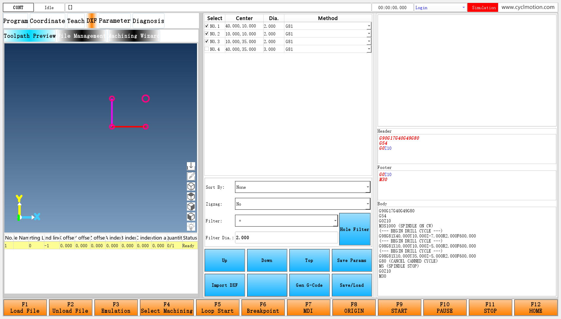
Click the screenshot to view the original image.
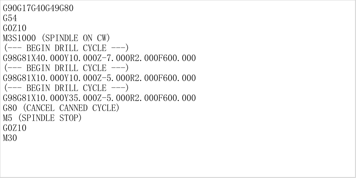
Click the screenshot to view the original image.
Here is the complete output. You can also download the generated NC text.
G90G17G40G49G80
G54
G0Z10
M3S1000 (SPINDLE ON CW)
(--- BEGIN DRILL CYCLE ---)
G98G81X40.000Y10.000Z-7.000R2.000F600.000
(--- BEGIN DRILL CYCLE ---)
G98G81X10.000Y10.000Z-5.000R2.000F600.000
(--- BEGIN DRILL CYCLE ---)
G98G81X10.000Y35.000Z-5.000R2.000F600.000
G80 (CANCEL CANNED CYCLE)
M5 (SPINDLE STOP)
G0Z10
M30
Match it to the inputs: 40,10 comes first at Z−7, followed by 10,10 and 10,35 at Z−5. Filtering excludes 40,35. Tool 0 produces no tool-change block, but M3S1000 remains.
The connecting lines show the hole-processing path, not the complete three-dimensional downfeed and return motion inside G81. Use the software's program preview and simulation on the saved NC file to inspect the cycle's motion.
Joining does not insert extra newlines. Without a newline at the end of Header, its final instruction can join the start of the generated section. Also, manual edits in Body are overwritten if you click Gen G-Code again: the script clears and rebuilds the text.
4. How Save/Load returns to the standard machining workflow
Check Body, click Save/Load, and enter a filename such as
dxf-drilling.nc.loadgcodefirst reads the editor's current contents:#6002.description=widgetFunc["PlainTextEdit","drillTextEdit","plainText",0]After file selection,
savefilewrites that text. The script then prepares data used by the program page:Setting Subsequent use #334.item[1]Add the saved file to the machining-file list #9047,#9048.channel,#9048.permissionSupply the code display with its path, starting display row and file line count #403Current machining-file path #810.permission=0Return to the Program main page 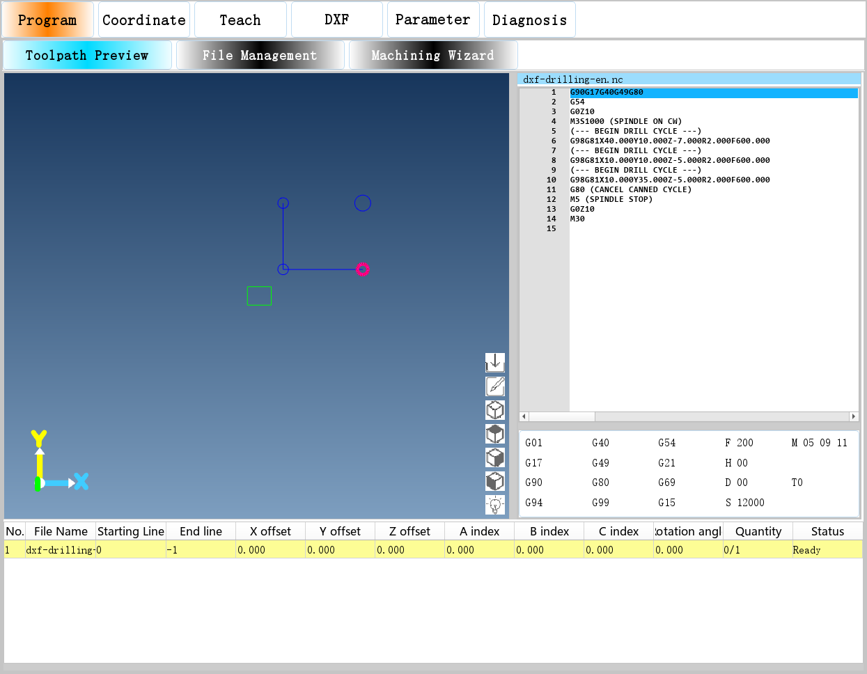
Click the screenshot to view the original image.
Figure 3: The NC text is loaded. Geometry retained on the left comes from the DXF stage; loading a file and simulating its NC motion are separate operations.
The editor's current contents are saved, including manual edits made before saving. The script also checks
#929.item[4], labelled Enable Reverse Processing in the English configuration. When it is 1, this save/load path requests simulation and reverse-path generation; when it is 0, it saves and loads only. That setting is off in this example.During machining or pause, the original script exits without performing Save/Load. Starting, pausing and resuming the generated program use the existing scheduling described in Start, pause, resume and stop.
5. Where to begin a DXF customization
Desired change Start with Relationship to preserve Show or hide the DXF entry #929.item[12]Change the item value in the macro parameter window Rename inputs or choices Parameter definitions, language packs, dxf.uiKeep both languages, input types and generated fields consistent Change defaults for future imports #6002,saveDrillParamDistinguish defaults from already imported per-hole values Change filtering or manual order holeselect,uppath,downpath,headpathAddress selection and settings through original hole indices Add fixed opening/ending blocks #6003.description,#6004.descriptionNewlines, coordinate selection, retract position and termination Change output formatting or machining statements processComplexVerticesMap.jsTen-field positions, point structure and the final returned string Add a per-hole setting UI, parameter definitions, import initialization, default saving, generation script and JS Connect every stage; an extra input box alone is insufficient The existing data route is:
DXF file → built-in reader → hole indices and centers
                                      ↓
Defaults → per-hole settings ← native table and inputs
                         ↓
                 filtering and ordering
                         ↓
         JS turns geometry and settings into NC text
                         ↓
           Header + generated section + Footer
                         ↓
              saved file → standard program page
Built-in geometry processing provides the base capability. Configuration decides what users enter and how per-hole data is organized. JS defines the generated program text. Following these handoffs shows which files a new requirement needs to change.
Follow one actual value through the design
Trace the original NO.2's Bottom Z −7 from input to output:
Stage Concrete value or action Click Center #9048.version=1remembers the original hole indexPress Enter in Bottom Z The lineEdit_4binding writes −7 to#6007.item[1]Move this hole to Top The first row becomes #6001.itemversion[0]=1; depth stays at its original itemBuild the settings string Generation reads −7 from #6007.item[1]into#6001.itemdesc[1]Prepare the generated task Center 40,10 and that hole's settings enter drill0:...togetherGenerate the JS drilling line parts[5]becomesfield5, producingZ-7.000Save/Load The complete Body text is read and written to the selected NC file This also gives an order for checking a customization: find where the input writes, inspect the settings string, then check which position JS reads. Changing the table, ordering and postprocessor simultaneously makes those relationships harder to follow.
Connect every stage when adding a setting
The current scripts use
#6002.itemnumas the number of settings and6003+setting indexto find each per-hole parameter. Appending an item to#6002therefore makes the import and saving loops access the next parameter number; it does more than add a row to the defaults. Confirm that the actual project has not allocated that number elsewhere. This chapter does not reserve#6013for unrestricted use.A complete extension defines the default, input type and bilingual labels; creates the per-hole items during import; places an input in the appropriate area using the original hole index; decides whether Save Params copies the value; fixes its position in the generated settings string; and makes JS read and use it. If consecutive parameter numbers no longer suit the design, adjust addressing in all three scripts: import, default saving and generation.
Practice tracing an existing setting first: find G82's
lineEdit_17, follow#6009.item[p]to the seventh setting, then locateparts[7]and its multiplication by 1000 in JS. This explains a complete setting without adding a control.For delivery, package only the changed UI, configuration scripts, language entries and postprocessor files. Provide installation steps that add only the required parameter fields. The existing
dxf-installimports whole parameter-definition files and helps trace their origin; do not repeatedly run it as an ordinary refresh on an existing configuration. See component package authoring, currently in Chinese.6. Continuing toward contour normal following
processNonDrillKeyin the existingprocessComplexVerticesMap.jsalready handles contour following. In that data route, a contour point'szis a precalculated tangent angle. Code generation uses processing such asC=z-90to obtain a rotary-axis angle; actual cutting depth comes from a separate setting.This differs from drilling-point Z and is not another way to fill the ten drilling fields. A page extension needs a matching pair of contour initialization/generation operations, inputs such as safe height, cut depth, feed and extension distance, and the correct contour data supplied to the existing JS branch. There is no need to begin by rewriting a normal-following algorithm. Enabling DXF alone does not give the standard drilling page contour inputs.
The connection points compare as follows. The right column is the direction for a subsequent extension; the standard page still uses the left column:
Stage Standard drilling Connection for normal following Build the list after import dxfDrillInitdxfContourInitGenerate dxfDrilldxfContourSettings string Ten drilling fields SafeZ:CutZ:Feed:Overcut: safe Z, cutting Z, feed, end extension or trimmingJS handler processDrillKeyExisting processNonDrillKeyPage contents Centers, radius filtering, drilling method Contour information and its settings; do not keep extracting radius from titles Program ending This example adds M30 in Footer The contour branch already adds a retract and M30; arrange the footer accordingly rather than appending it after M30 Both initialization operations use
#6001for their object list. A mode-switch design must rebuild the appropriate list rather than interpreting the previous mode's hole indices and settings as contours. This requires connecting a complete page flow, not merely replacing one function name in Gen G-Code.The existing normal-following design notes describe that connection in detail. For AI-assisted postprocessor changes, use the prompts based on the actual data format, preserving the input positions and output rules explained here. These supplementary design notes are currently in Chinese.
7. Troubleshooting
Symptom First check Body contains only Header and Footer Check selected holes and valid drilling types, then the JS path and syntax NC hole order differs from the table Check sorting, tool groups and string order for multi-digit task numbers Manual changes in Body disappear Check whether Gen G-Code was clicked again Header and the first generated statement share one line Retain the final newline in Header Save/Load does nothing Check machining/pause state; cancelling file selection also prevents saving With the route from page input through per-hole settings and JS to NC text established, the next chapter adds G196 bore milling to the existing page.
Previous lesson: Hole table and settings · Reading guide · Next lesson: G196 bore-milling example
在线咨询 - Download
