
- 首页
- About
- Products
- Download
- Support
- Applications
Secondary Development
Machining Wizard: how dimensions become a rectangular toolpath
Download the bilingual offline manual (ZIP, 16.7 MiB, original images and example attachments)
Teach builds a program one record at a time. The Machining Wizard uses another approach: the operator enters dimensions and machining parameters, and an existing macro calculates the complete toolpath.
This lesson follows the standard Carving Rectangle function: where to enter values, where they are stored, how Load File calls the macro, and how its loops become individual motion lines. You can understand this existing design without adding pages, buttons or parameters.
1. Find the function in the standard interface
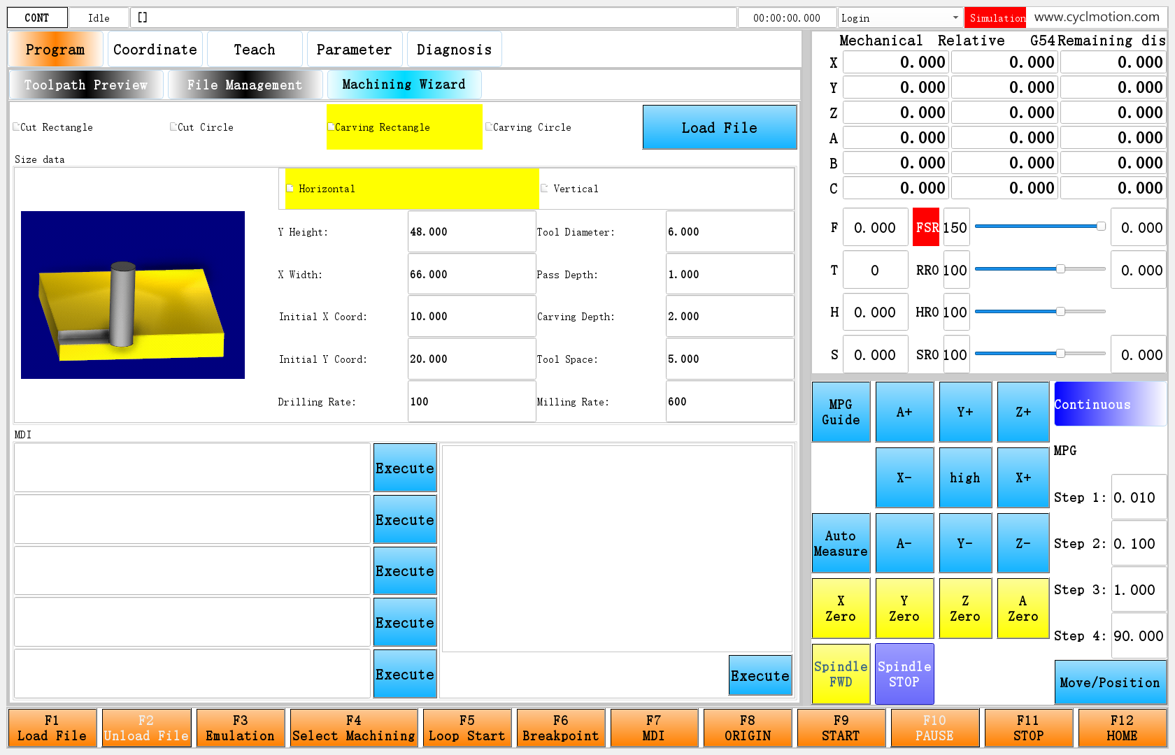
Open Program → Machining Wizard → Carving Rectangle. The top row selects the operation. Size data contains the dimensions and rates, and the illustration on the left shows the selected cutting direction.
Click the screenshot to view the original image.
Figure 1. The original wizard inside the Program page. The upper-right label reads Simulation. This lesson uses Size data and Load File above it; the MDI area below has separate Execute buttons.
Here, Load File generates a toolpath from the current inputs and then loads the result. It does not open a dialog for selecting an existing file, as File Management does.
2. Enter dimensions that are easy to check
Select Horizontal and enter the following values. Press Enter or leave each field to write the value back to its parameter.
Label in the English interface Example value Meaning in this example Y Height: 48 Rectangle size along Y X Width: 66 Rectangle size along X Initial X Coord: 10 X coordinate of the rectangle's starting corner; the tool center adds the radius Initial Y Coord: 20 Y coordinate of the starting corner; the tool center adds the radius Tool Diameter: 6 Used directly to calculate the center path Pass Depth: 1 Produces two depth levels in this example Carving Depth: 2 Enter a positive depth; the macro generates negative Z positions Tool Space: 5 Distance between adjacent passes; smaller than the tool diameter here Drilling Rate: 100 F value used for plunging in the macro Milling Rate: 600 F value used for milling in the macro 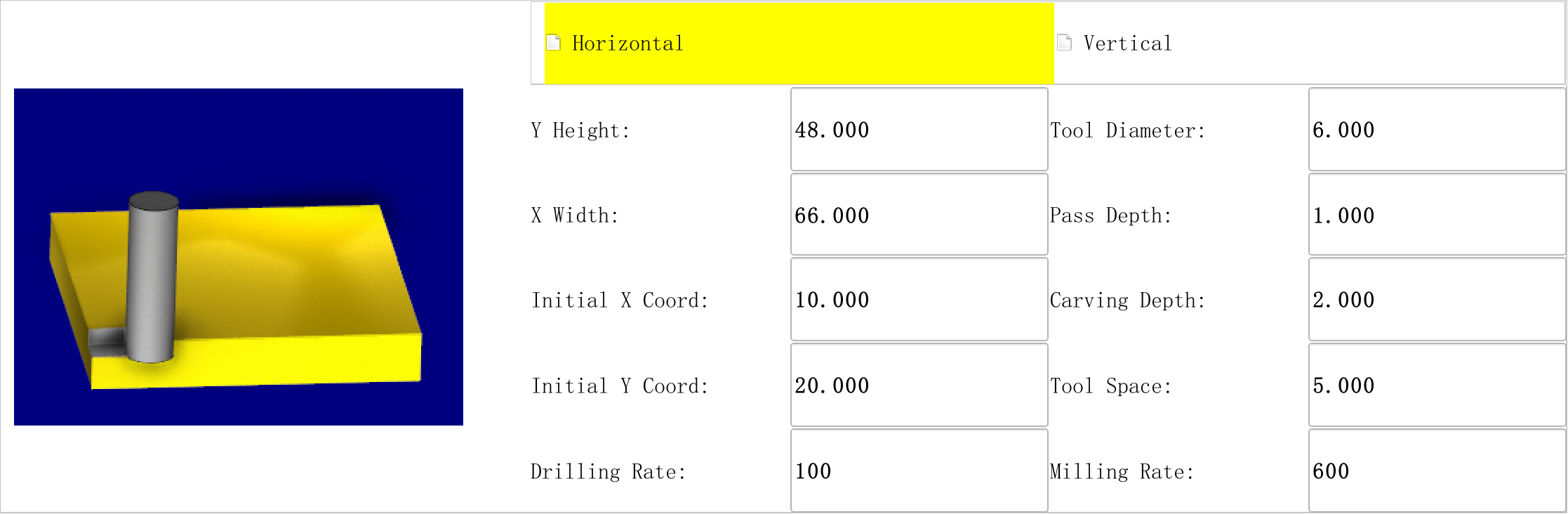
Click the screenshot to view the original image.
Figure 2. A close-up of Size data. Click the image in the illustrated edition to enlarge it.
These values illustrate the calculations; they are not cutting recommendations for a particular material or tool. Dimensions and feed rates must use the machine configuration's current units. Neither the macro nor the output file adds G20/G21 to change units.
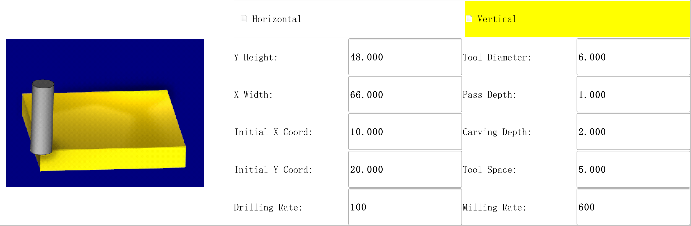
Selecting Vertical keeps the values and changes both the direction selection and the illustration.
Click the screenshot to view the original image.
Figure 3. Both directions use the same dimension fields. Select Horizontal again before continuing with the code below.
3. What should appear after Load File
When the system is idle and Reset has been released, click Load File above the dimensions. After generation, the page returns to Toolpath Preview, the current file becomes
矩形铣底.nc, and the code area displays the expanded motion commands.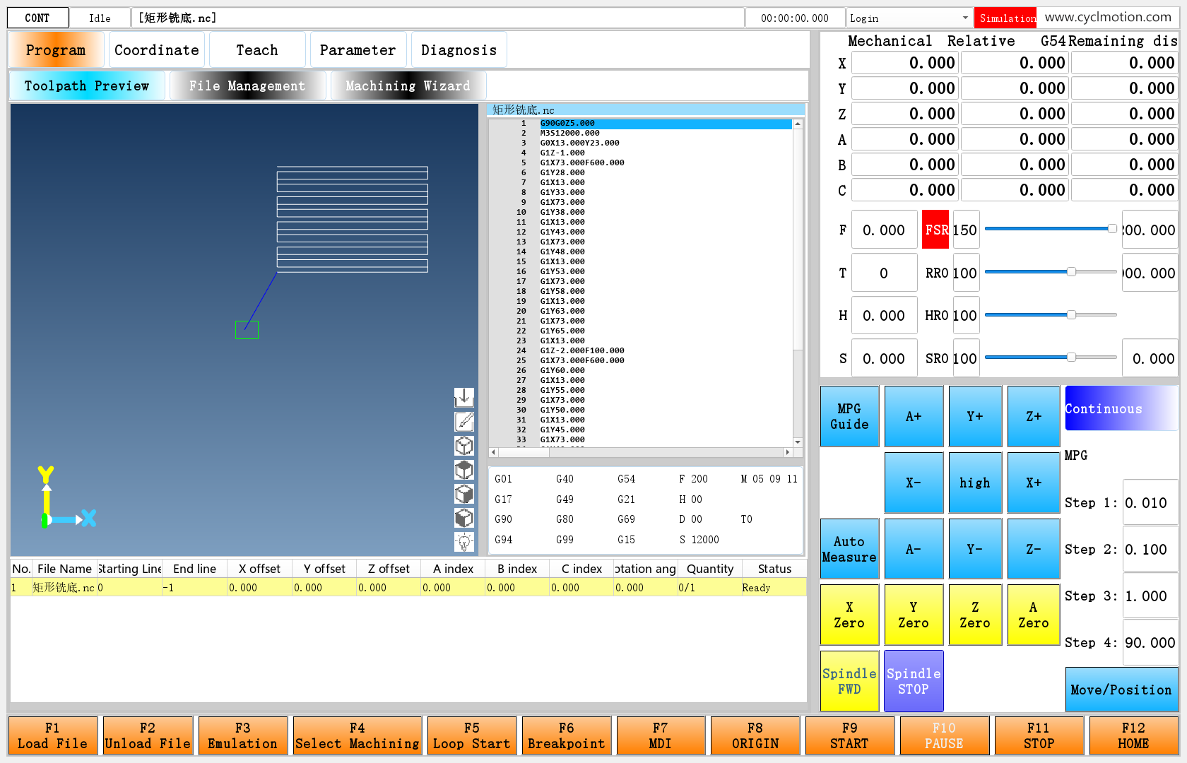
Click the screenshot to view the original image.
Figure 4. The path uses the values in Figure 2. A top view and an adjusted zoom show the path clearly. The two depth levels overlap in this view; inspect the Z values in the code as well.
The generated filename remains
矩形铣底.ncin the English interface because the standard script sets that literal filename. Changing the interface language does not translate the script's output path.The beginning of this file, shown as non-empty lines in the code area, is:
G90G0Z5.000
M3S12000.000
G0X13.000Y23.000
G1Z-1.000
G1X73.000F600.000
G1Y28.000
G1X13.000
G1Y33.000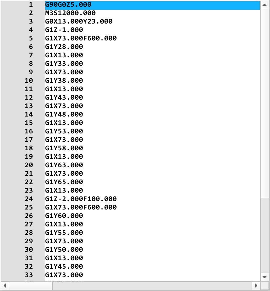
Click the screenshot to view the original image.
Figure 5. The values 13, 23, 73, Z−1 and Z−2 can all be calculated from the inputs. The complete generated file accompanies this lesson.
This stage generates and inspects the file. To machine it, follow Start, pause, resume and stop and confirm the work coordinates, tool, spindle, clearance height and feed rates.
One detail in the current output needs particular attention: the first plunge,
G1Z-1.000, has no explicit F value. The second plunge later containsG1Z-2.000F100.000. That later F100 does not establish the feed used for the first plunge. Before execution, make the initial cutting feed explicit. If it must be added, save a separate machining copy and add the required F value there. Generating again overwrites the standard output filename.4. Follow the files in operation order
These paths are relative to the software's runtime directory, not the folder containing this book's attachments.
File Responsibility env/program/advancedpageLoads the wizard on first entry and prepares the MDI area and initial illustration env/program/advanced.uiOperation choices, dimension fields, direction controls and Load File env/funcscripts/generatecodeSelects the macro, sets the output name and requests generation env/macroMillRect.ncReads rectangle parameters and calculates tool-center positions, depth levels and traverses env/timerTakes the result after the generation sequence becomes idle and switches to Toolpath Preview The direction illustration is selected by
env/program/advanced/millrect. Read the complete flow as:Enter #2009 values → click Load File → generatecode selects macroMillRect.nc → the macro calculates motion → the software writes 矩形铣底.nc → timer loads the result.
The page settings and
generatecodeare configuration scripts.macroMillRect.ncis an NC macro. The configuration script chooses the source and destination; the macro calculates the path. Sending the generation request does not make the button script wait for the whole path to finish.5. Two selection values control two different page levels
Page switching introduced
#810, which selects Toolpath Preview, File Management or Machining Wizard.Inside the wizard,
#812selects the operation:#812 English operation label Input parameters Calculation macro Output filename 0 Cut Rectangle #2007 macroCutRect.nc割方形框.nc1 Cut Circle #2008 macroCutCircular.nc割圆形框.nc2 Carving Rectangle #2009 macroMillRect.nc矩形铣底.nc3 Carving Circle #2010 macroMillRound.nc圆形铣底.ncThis lesson examines the rectangle operation in detail; the other rows show how the shared entry is organized.
The click setting on
label_3, the Carving Rectangle control, is:-A: (clickedEvent:/env/program/advanced/millrect[0](#812=2))It sets
#812to 2, then runsmillrectto prepare the illustration. The rectangle input area,frame_3, uses:-C(#812==2) -V0That area appears when the rectangle operation is selected. The other operations use the same approach, allowing one UI file to contain four different input groups.
Distinguish the main value of
#812from its other fields:#812.versionrecords page preparation,#812.itemdesc[0]holds the UI path, and#812.permissionmarks the result that must be handled after generation. Each serves a different step.6. How an input connects to a macro variable
The X Width input,
lineEdit_13, has these properties:-T(#2009item2) -DHere,
#2009item2refers to the field written as#2009.item[2]in scripts.-Tidentifies the parameter to display and edit;-Drefreshes the control when the parameter changes. This ordinary input writes back to the field when confirmed, without a separate button script to calculate X Width.Its adjacent label reads
#2009.itemtitle[2]. Thus X Width: and 66 come from different fields of the same parameter item. A language change can replace the title while keeping the numerical storage unchanged.#2009 field Interface purpose Local variable read by the macro item[0]0 Horizontal, 1 Vertical #9 item[1]Y Height #6 item[2]X Width #5 item[3]Initial X Coord #1 item[4]Initial Y Coord #2 item[5]Tool Diameter #8 item[6]Pass Depth #4 item[7]Carving Depth #3 item[8]Tool Space #7 item[9]Drilling Rate #30 item[10]Milling Rate #31 These parameters already exist in the standard configuration. Do not allocate #2009 again for this lesson. Also, do not infer indices from visual order: Y Height appears first, but X Width uses index 2.
7. One direction parameter controls both illustration and calculation
Horizontal assigns
#2009item0=0; Vertical assigns#2009item0=1. Both then callmillrect.This is the complete script, with the original filenames retained:
IF#2009.item[0]==0GOTO1 widgetFunc["Label","millRectLabel","setMovie","images/纵向矩形铣底.gif"] GOTO2 N1 widgetFunc["Label","millRectLabel","setMovie","images/横向矩形铣底.gif"] N2 widgetFunc["Label","millRectLabel","playMovie",0]setMovieselects an animation for the existingmillRectLabel;playMoviestarts displaying it. Each direction has an existing GIF. These illustrations explain direction; they are not recalculated from the current 66 × 48 dimensions.The calculation macro reads the same field:
#9=#2009.item[0];路径方式 #9 0-横 1-纵 #9The original comment identifies 0 as horizontal and 1 as vertical. Later,
IF#9==1GOTO20selects the vertical branch. Selection, illustration and calculation therefore share one value. Replacing the animation alone does not change the generated path.8. How Load File starts generation
8.1 What the button script prepares
The complete operation properties of
pushButtonare:-T(#1100itemtitle50) -C(#319item3==1||#319item7==1) -E0 -A: (clickedEvent:/env/funcscripts/generatecode[1]) -DThe caption comes from a shared text parameter. The button is disabled while running or paused; clicking it runs
generatecode. Keep the standard event-channel setting. It is a different numbering scheme from the operation choices 0, 1, 2 and 3.generatecodechecks whether the interpreter is busy, then selects a branch using#812. This is the original rectangle branch, including its original comments:N2 #331.item[2]=1;清除画板 #100=#405+"macroMillRect.nc" #334.itemnum=0 #334.item[1]=#100 #9047=#100 #9048.channel=0 #9048.permission=widgetFunc["getFileLineNum","","",#100] #403=#100 #319.item[17]=1;生成路径代码 #319.item[18]=0;正向路径代码 #319.item[19]="矩形铣底.nc";路径代码名称 #319.item[20]=0;关闭逆向加工 #319.item[4]=1;宏解析 IF#324.item[12]==1THEN#319.item[11]=1;仿真 #319.item[10]=0;MDI #319.item[9]=0;取消恢复加工 #319.item[3]=1;解释器启动 #812.permission=1;设置生成代码标志,定时脚本中处理 GOTO1This is an excerpt containing the rectangle branch. The original file also contains the earlier selection logic and final
N1. Do not save this excerpt as a replacement script.Read it in three parts:
#100receives the source macro path.#334,#403,#9047and related fields prepare the current file and code display.- Items 17–20 of
#319select code generation, forward output, destination name and the reverse-machining switch. Item 17 is the generation flag; it is different from the simulation flag at item 11. - The script selects macro parsing, starts in non-MDI mode and sets
#812.permission=1for later result handling. Although the original comment on item 10 says MDI, its assigned value is 0: read the actual assignment as non-MDI.
The source is an NC macro, not an immediately executed configuration script. Its IF, GOTO and WHILE statements require an initial structure scan to associate labels and loop boundaries before calculation. Machining controls explains this distinction between file-processing modes.
8.2 Which settings turn macro execution into file generation
First select code-generation mode, then let the NC interpreter execute the macro.
generatecodeprepares the settings; the software's built-in NC interpreter calculates the path and writes the file.macroMillRect.ncdoes not need a separate file-writing call for each output line.Read these settings together:
Setting Role in this generation pass #403=#100Select the input: the path to macroMillRect.nc#319.item[4]=1Scan the program structure, then execute expressions, branches and loops as an NC macro #319.item[10]=0Select file execution; this path-to-code handling requires non-MDI mode #319.item[17]=1Enable path-code generation, collecting calculated ordinary motion segments as G-code text #319.item[18]=0Generate in forward order; this is independent of Horizontal/Vertical #319.item[19]="矩形铣底.nc"Name the output file; this path serves a different purpose from the input macro in #403 #319.item[20]=0Read the original source rather than run the reverse-machining file #319.item[3]=1Request NC execution after the preceding settings are ready The software reads these fields directly as control values. The NC scheduling thread receives the request; the button script can then finish while calculation continues in the NC interpreter. Select the input and generation settings before requesting a start.
Simulation and code generation are separate settings.
#319.item[11]controls simulation, whereas#319.item[17]controls generation. Selecting Simulation alone does not create矩形铣底.nc. Assigning a filename to item[19] alone does not trigger generation either.8.3 What the software does internally
A normal rectangular-generation pass proceeds as follows:
- Read the source macro. The NC scheduling thread finds the file through #403. Macro mode first scans its labels and loop boundaries.
- Execute the calculations. Read #2009, calculate variables such as #1 and #11, and execute IF, GOTO and WHILE. Each loop iteration calculates its corresponding moves.
- Convert motion results to text. G0/G1 first produce motion segments with start points, end points and feeds. With non-MDI mode and the generation flag set, the software converts this example's ordinary motion segments to G-code lines and keeps them in an in-memory list. These segments bypass normal motion dispatch.
- Write the file. After source-file parsing returns, the software opens the output named by item[19], writes the header, collected lines and ending, then closes it.
- Finish and load the result. After normal completion handling,
timerreceives the file and changes the page. Section 10 explains this handover.
The NC macro still executes: assignments, conditions and loops have their usual effects. What changes is where the ordinary path results go. The generation flag does not disable every external operation in an arbitrary macro. When extending a wizard, follow this example's dimension calculations and motion statements, and separately examine any M-codes, I/O or external calls you add.
9. How the macro turns 66 × 48 into traverses
The complete original macroMillRect.nc accompanies this lesson. Follow the calculations rather than trying to memorize every local variable number.
9.1 Read the inputs and calculate the tool center
After reading the parameters listed in Section 6, the macro uses:
G0X#1+#8/2Y#2+#8/2The radius is 3, giving the first XY position
(10+3,20+3)=(13,23). The input defines the rectangle's starting corner; the tool center starts one radius inward.Next it calculates the center's available travel:
#11=#5-#8
#12=#6-#8
This gives
66−6=60along X and48−6=42along Y. The example's tool-center limits are X13–73 and Y23–65. The diameter is subtracted directly; this calculation does not pass the tool diameter to G41/G42.9.2 Use a loop for horizontal traverses
The horizontal branch first calculates:
#13=ROUND[#12/#7]+1
#14=#12-[#13-1]*#7
Here,
42/5=8.4, which rounds to 8. Thus #13 is 9 and the remaining #14 is 2. The complete inner-loop excerpt is:#15=#13 WHILE#15>0DO1 G91X#11F#31 #11=-#11 IF#15==1GOTO2 G91Y#7F#31 N2#15=#15-1 END1The first traverse moves 60 along X. Changing #11 to −60 reverses the next X move. Each iteration except the last also steps 5 along Y. #15 decreases by 1, ending the loop after nine traverses.
After the loop, the macro executes:
G91Y#14F#31
G91X#11F#31
#11=-#11
#7=-#7
#14=-#14
It covers the remaining 2 along Y and makes another X traverse. It then reverses the Y step and remainder so the next depth level can return from the opposite side. Copying only the WHILE loop would omit this remainder handling.
9.3 The outer loop controls depth
The macro takes the smaller of Pass Depth and Carving Depth as the first depth #16, then executes:
N11G1Z-#16F#30The first level is Z−1. After completing that level, #16 increases by Pass Depth. If this exceeds the total depth, it is limited to the total. The second level in this example is therefore Z−2.
The horizontal outer loop uses
WHILE#16<=#3DO2, with #16 changed to leave the loop at completion. The vertical branch uses DO4 for depth and DO3 for Y traverses. Vertical travels 42 along Y and steps along X; changing only a displayed direction label cannot implement that behavior.9.4 The expanded file no longer needs the local variables
The macro's
G91X#11becomes absolute positions such asG1X73.000andG1X13.000. The generated file starts with G90. Do not infer incremental execution of the output from G91 in the source macro.The software writes G-code from the calculated motion segments. Consequently, this output does not retain the macro's WHILE, IF or #11 statements, nor does it simply copy every macro statement once.
Compare a few steps from the first depth level:
Step in the macro Calculated result Content written to the output G0X#1+#8/2Y#2+#8/2Tool center reaches X13, Y23 G0X13.000Y23.000First execution of G91X#11F#31Add 60 to X13, reaching X73 at F600 G1X73.000F600.000#11=-#11Change the next X increment to −60 This assignment itself produces no motion-code line G91Y#7F#31Add 5 to Y23, reaching Y28 G1Y28.000Next execution of G91X#11F#31Add −60 to X73, returning to X13 G1X13.000One source line can therefore produce many different output lines. The software writes this example's calculated absolute coordinates, omitting unchanged coordinate words and some repeated F values. The first plunge without explicit F, discussed in Section 3, is a detail to check in the output; seeing
F#30in the source is insufficient.Likewise, M3 and M30 inside
#5996.titleanddescriptionare string contents prepared for the output file. Assigning those fields does not execute the M commands inside the strings. These text fields explicitly supply the header and ending commands that the result needs.10. File header, file ending and completion handling
10.1 Where the header and ending come from
Besides reading dimensions, the macro sets two text fields:
#5996.title="G90G0Z"+#330.item[56]+" M3S"+#330.item[14]+" " #5996.description="G90G0Z"+#330.item[56]+" M30 "#5996.titlesupplies the header, and#5996.descriptionsupplies the ending. For forward generation, the software writes header → calculated motion code → ending. In this example they produce Z5 and S12000. Those two values come from machine parameters in #330, not from the Size data fields in Figure 2.When reading a wizard, identify both its page inputs and its other parameter sources. Copying only the central loop cannot reproduce the complete standard result.
10.2 When the file is actually written
This example's motion code is collected in memory and written to disk after source-macro parsing returns. The built-in NC processing writes the file.
generatecodesupplies the settings, andtimerreceives the resulting file.For normal completion, follow this order:
Order What happens Meaning at this point 1 Execute macroMillRect.ncand collect motion codeGeneration is still in progress; an older file with the same name is not the new result 2 Open the item[19] path, write header, motion code and ending, then close The output has gone through file writing 3 Schedule end.nc, thensafez.ncfor completion handlingThe standard scripts recognize generation mode and skip the relevant normal-machining actions; safez.ncclears the generation flag and cancels a further start4 NC execution finishes and timerhandles#812.permissionLoad the result and select Toolpath Preview This explains why the button script must not read the result immediately after requesting a start, or immediately clear item[17]. The standard completion sequence ends generation mode; preserve that handover.
Writing replaces an existing file with the same name without automatically backing it up. After an abnormal interruption, the built-in writing branch may still write the partial code collected so far. A file's existence, an idle state or a page change alone does not establish complete generation. Check alarms, dimensional limits, depth levels, and the code's header and ending against the intended result.
10.3 Why the button script does not immediately load the result
Generation takes time.
#812.permission=1means a result must be handled later; it does not mean the file has already been written.In
env/timer, this work lies after the check that skips idle processing while the interpreter is running:IF#319.item[3]==1GOTO1Once idle processing is reached, the result section checks:
IF#812.permission==0GOTO1
#812.permission=0
#334.itemnum=0
#334.item[1]=#319.item[19]
#9047=#319.item[19]
#9048.channel=0
#9048.permission=widgetFunc["getFileLineNum","","",#319.item[19]]
#403=#319.item[19]
#5999.itemnum=0
#[6001+#9047.permission].itemnum=0
#810.permission=0
#810=0
These are excerpts from two locations; joining them does not create a replacement for the complete timer. The result section clears the pending flag, loads the output path, updates the code area and selects Toolpath Preview with
#810=0.The output name
矩形铣底.nccontains noenv/prefix. It is relative to the software's current working directory; it does not overwriteenv/macroMillRect.nc. Generating the same operation again writes the same output name, so save a separate copy to keep an earlier result.The following
#929.item[4]check can request another generation pass for reverse machining, writingplanning.ncwith reverse output selected. This later processing is distinct from Horizontal/Vertical in Size data. It is disabled for this example.11. Where to start when adapting an existing wizard
Desired change First place to inspect Also check Page or input captions UI text sources, #2009.title and itemtitle Both language files; changing design-time UI text alone may have no effect Input storage The QLineEdit -T(...)fieldThe macro must read the same field Direction illustration advanced/millrectand the original GIFsThe illustration must agree with the calculation branch Depth, spacing or traverse rules macroMillRect.ncLocal variables, remainders, loop exit conditions and final limits Output filename #319.item[19]ingeneratecodeOverwriting, path location and result loading Header and ending The two #5996 text fields Clearance, spindle, units, coordinates and initial cutting feed Change one clear requirement at a time and compare code and preview using small, easily calculated dimensions. Inputs, illustrations, the macro and the output text each have a specific job. Find the part that actually determines the behavior you want to change.
12. Troubleshooting
Symptom What to check Changed dimensions but the old result remains Confirm the input, then click Load File again; editing parameters does not rewrite the output automatically Load File is disabled Check for running or paused state The button accepts a click but generation does not start Check whether Reset remains active; the button condition does not cover every NC execution condition The page switches but the file is empty or unexpected Check generation alarms, output path and write access; the pending flag and page switch do not prove a valid file The illustration changes but the calculated direction does not Follow #2009.item[0], #9 and the macro branch; replacing a GIF alone is insufficient The path is smaller than the input rectangle It is the tool-center path; one tool diameter is subtracted from each overall dimension A top view appears to show only one level The XY paths overlap; inspect Z−1 and Z−2 or change the viewing angle The initial plunge feed is unclear Check for an explicit F before or on the first G1 line Before generating, also check that the diameter is smaller than both dimensions and that pass depth, total depth, spacing and rates are reasonable positive values. The original macro does not provide a dedicated message for every invalid combination. Zero spacing creates a division problem, and zero pass depth cannot provide normal progress through the depth loop.
The remainder calculation uses ROUND, not an unconditional downward rounding. With different dimensions, check the last step and limits using the actual formula. The positive remainder of 2 in this example does not imply that every input combination produces a positive remainder.
You can now connect a standard page, its parameters, an NC macro, the output file and the loading operation. The next topic is DXF: how drawing data can feed into the same program-use workflow.
Previous: Edit, save and reopen · Reading guide · Next lesson: DXF page and import
在线咨询 - Download
